


I wish there were more examples of SFD and BMD… with clear, easy-to-follow explanations.
Wish you could see a variety of SFD and BMD problems—and how to solve them step by step?
Up to this point, we’ve covered the fundamentals of SFD (Shear Force Diagram) and BMD (Bending Moment Diagram)—including how to construct them and the key characteristics they exhibit.
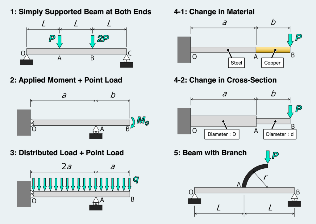
In this article, we’ll walk through six different practical examples to further explore how to draw SFDs and BMDs, and how their shapes change depending on loading conditions. By going through these cases, you’ll develop a deeper, more intuitive understanding of how these diagrams work.
If you’ve been following along, great. If not, here are the previous articles on SFD and BMD for reference:
How to Draw SFD & BMD: Worked Example and Step-by-Step Solution
How Different Loads Appear in Shear Force and Bending Moment Diagrams (SFD and BMD)
How to Draw Shear Force and Bending Moment Diagrams (SFD & BMD) Step by Step
Shear Force Diagram & Bending Moment Diagram (SFD/BMD): What They Are and Why They Matter
- If you follow the step-by-step procedure, you’ll be able to draw SFD and BMD correctly for any problem.
- You’ll understand the key characteristics that appear in SFD and BMD—and learn to check whether your diagrams properly reflect them.
- Changes in material or cross-sectional shape do not need to be considered when simply drawing SFD and BMD.
*This is a fairly long article—so feel free to check the images and table of contents below, and dive into whatever sections catch your interest.
渾身のnoteを書きました!!

「公式は覚えてるのに問題を見たら手が止まる…」
そんなあなたは『解法の型・流れ』を理解できていないのです。材料力学は色々な問題がありますが、実は決まった型に沿って解くことができ、この型こそが材力の基礎であり極意であると言えます。
このnote記事は、本ブログ管理人のぽるこが「材料力学の問題を解く上での型・要点・コツ」を本気でまとめあげました。かなりの大ボリュームかつエッセンスを詰め込んだものですが、1,200円という映画1本分にも満たない価格設定としました。
本ブログに書ききれていない内容も多く含んでおりますので、ぜひ読んでみてください!
First, let’s quickly review the process.
The step-by-step procedure for drawing an SFD and BMD is as follows:
Isolate the entire beam from its supports and treat it as a free body.
Then, use the equilibrium equations to calculate the support reactions.
For cantilever beams, you can skip this step.
Scan the beam from left to right.
Whenever there is a point where the loading or conditions change, you need to divide the beam into sections.
Cut the beam at an arbitrary location and create a free body.
At the cut section, you can introduce the internal forces: shear force F and bending moment M.
Their directions (positive directions) should be assigned according to the rule—don’t worry, we’ll go over the rules later.
At this stage, it does not matter whether the actual internal forces act in those directions or not.
Let the distance from the left end of the beam to the cut section be x.
Apply the equilibrium equations to the free body you just created.
This allows you to determine the internal forces acting at the cut section located at position x.
The shear force F and bending moment M are obtained as functions of x.
If you divided the beam into multiple sections in Step 2, repeat Steps 3 and 4 for each section.
Plot the results on graphs with x on the horizontal axis and either F or M on the vertical axis.
At key points—such as boundaries between sections—substitute specific values of x to calculate F and M, and use those values to sketch the diagrams.
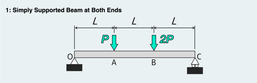
Let’s start with a beam that is simply supported at both ends.
Following the usual procedure, the first step is to find the reaction forces at points O and C. To do this, isolate the entire beam as a free body—that is, separate it from the supports—and apply the equilibrium conditions.
The key point here is that the types of reaction forces depend on the support conditions. So before drawing the free-body diagram, make sure to identify the support type correctly and include only the reaction forces that can actually occur at each support.
If you want a quick review of support types and the corresponding reaction forces, check out the article below.
![[thumbnail]_Vol1-2-2en](https://secondinspire.com/wp-content/uploads/thumbnail_Vol1-2-2en-min-160x160.png) The concept of the free body_Types of support (vol.1-2-2)
The concept of the free body_Types of support (vol.1-2-2)
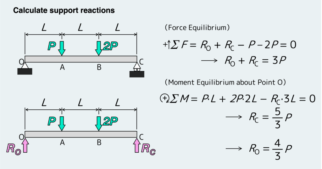
In this example, point O is pinned support and point C is roller support, so only vertical reaction forces are generated. Based on that, the equilibrium equations become as follows:
The next step is to decide where to divide the beam into sections.
You need to divide the beam wherever the loading condition changes. In this case, external loads are applied at points A and B, so those two points become the boundaries.
That means we’ll consider the shear force F and bending moment M in the following three sections: OA, AB, and BC.
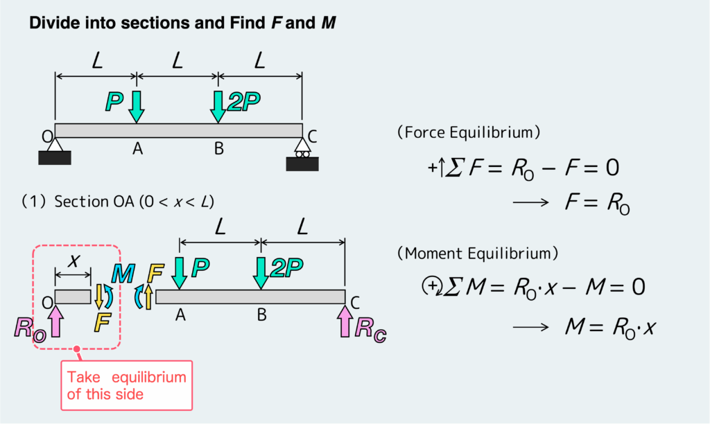
Let’s start with the section OA, that is, when 0 < x < L.
The key idea here is simple: when applying the equilibrium equations, choose the free body that makes the calculation easier.
If we virtually cut the beam at an arbitrary position within section OA and draw the free-body diagrams, we obtain two separate free bodies, as shown below.
But clearly, it’s much easier to apply the equilibrium conditions to the left-hand side, right?
By applying the equilibrium equations to this free body, we can determine the shear force F and bending moment M in this section.
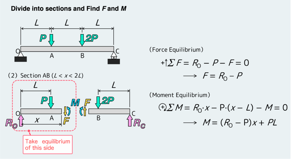
Next, consider the section AB, that is, L < x < 2L.
Applying the equilibrium conditions gives the following:
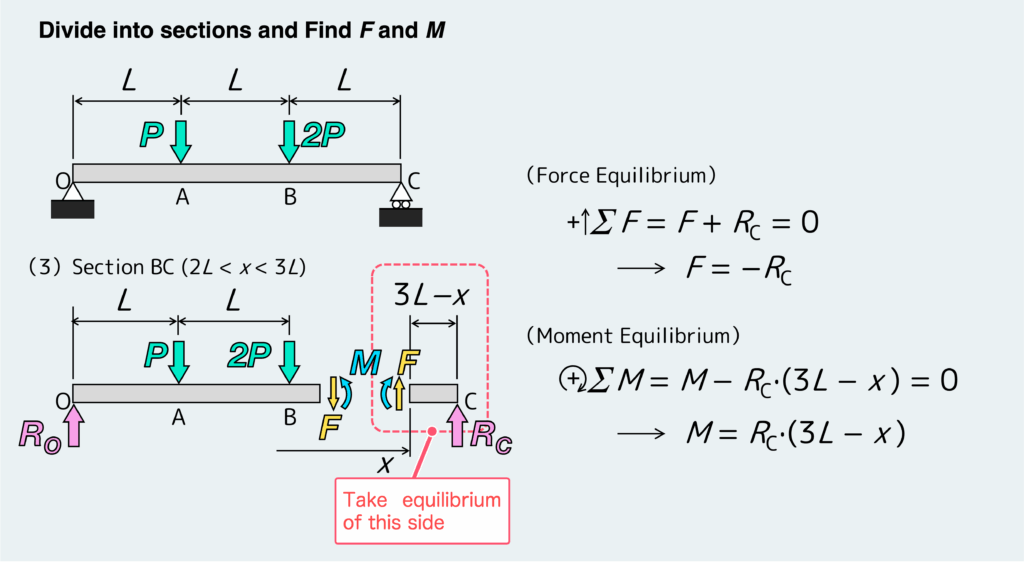
Finally, we move on to the section BC.
Applying the equilibrium conditions, the shear force F and bending moment M are obtained as follows:
Now that we’ve gone through all the steps, let’s put everything together and draw the SFD and BMD.
When drawing the diagrams, try to be as accurate as possible. Doing so helps prevent careless mistakes and unnecessary errors.
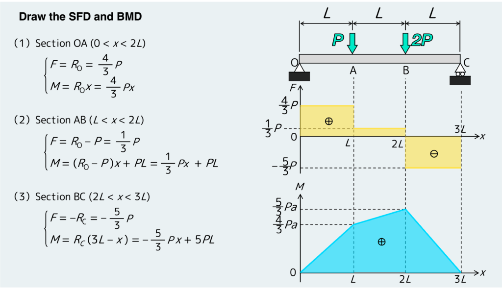
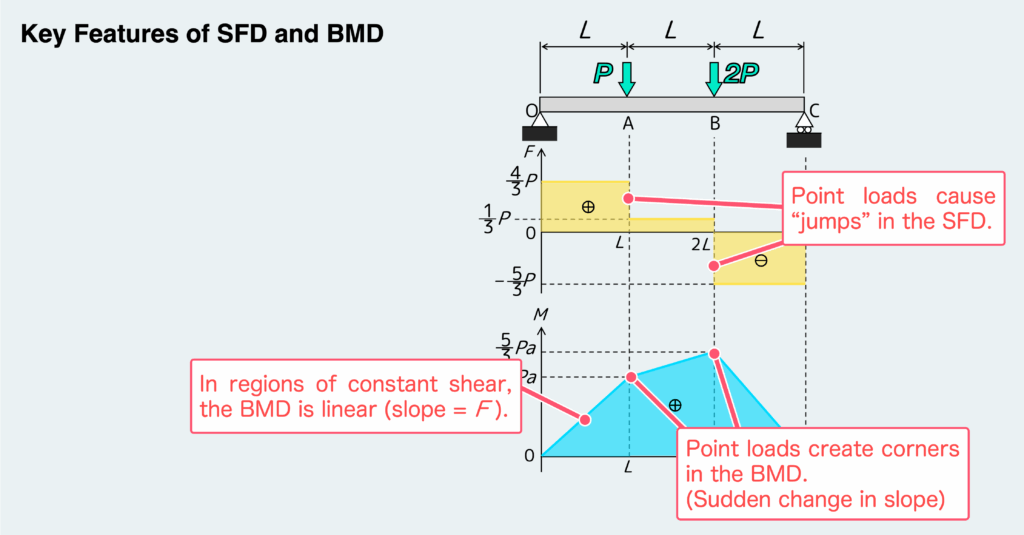
If you can draw the SFD and BMD like this, you’ll see that point B is the most critical location on the beam.
Assuming a uniform cross-section, the bending moment required to calculate the maximum bending stress at this point is “5P/3“.
Finally, let’s check whether the characteristic features we discussed in the previous article actually appear in the SFD and BMD.
As shown below, at points A and B, where concentrated loads are applied:
- the SFD shows a sudden jump (discontinuity)
- the BMD shows a corner
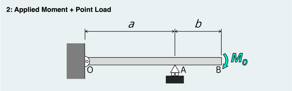
Now, let’s move on to the next example—this time, a beam subjected to a moment.
By the way, you might be wondering:
“What does it even mean for only a moment to act on a beam?”
That’s actually a very reasonable question.
It’s easy to visualize a point load, but a moment acting by itself is a bit harder to picture.
Can we really apply a moment without applying any force?
The answer is shown in the figure below.
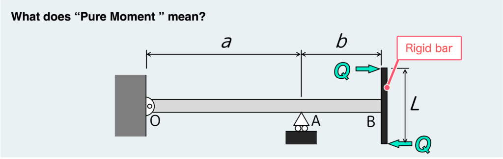
A moment is always generated by a couple—a pair of forces with equal magnitude and opposite directions.
In this case, the pair of forces Q produces the moment.
Now, if we isolate only the rigid bar attached to the end of the beam, we can see how the internal forces are transmitted, as shown below.
モーメントってのは必ず偶力という力のペア(同じ大きさで反対向きの2つの力)によって生み出される。
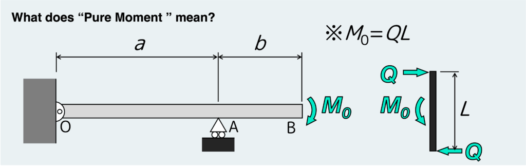
If we define QL = M₀, this setup becomes equivalent to the original problem, where a moment M₀ is applied at the end of the beam.
So in reality, a “pure moment” never exists on its own—there is always an underlying couple generating it.
However, including that in every problem would make the diagram unnecessarily complicated, so it is usually omitted.
Alright, now that we’ve cleared that up, let’s get back to the SFD and BMD.
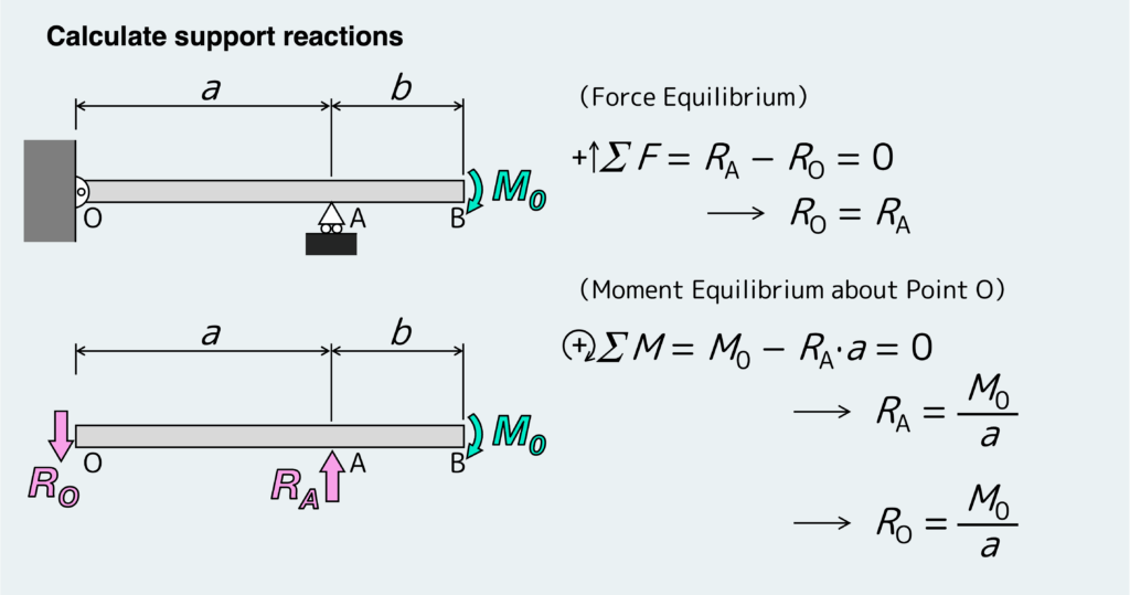
First, we determine the reaction forces shown below.
As mentioned earlier, the key point is that the possible reaction forces depend on the support conditions.
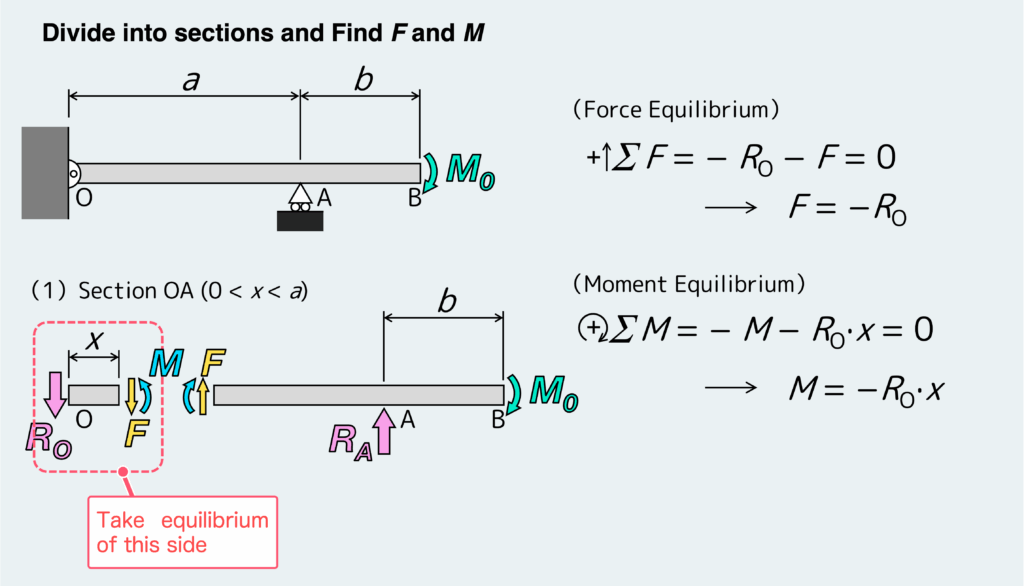
Next, we divide the beam into sections and apply the equilibrium conditions to each one.
In this case, there is a support at point A, which introduces a reaction force.
So we divide the beam into two sections: OA and AB.
First, we virtually cut the beam within section OA.
Then, we apply the equilibrium conditions to the resulting free body to determine the shear force F and bending moment M acting on that cross-section, as shown below.
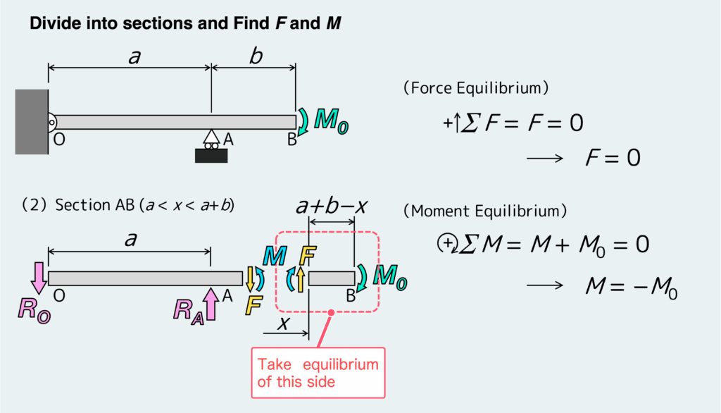
Next, we repeat the same process for section AB, which gives the following result:
Using the obtained F and M, we can plot the SFD and BMD as shown below.
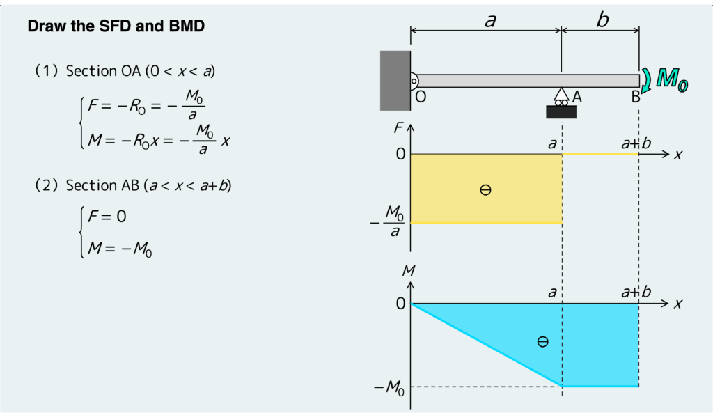
From these SFD and BMD, we can observe the following features:
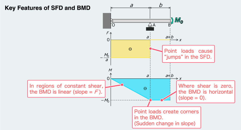
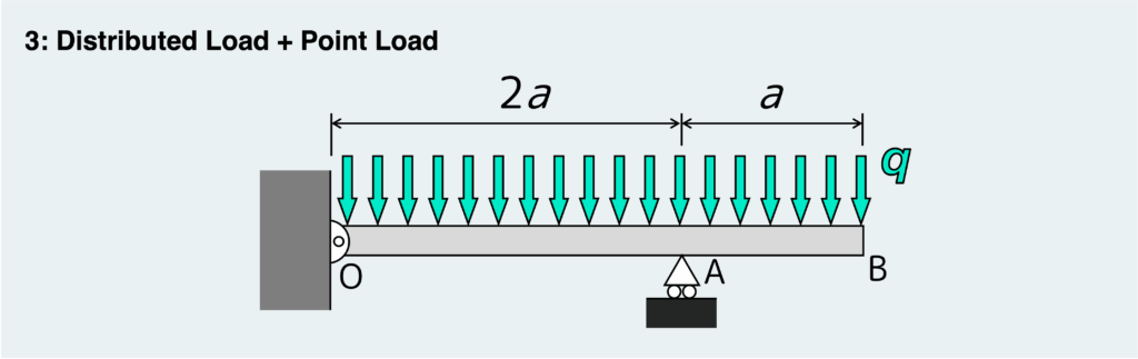
Alright, let’s move on to a beam problem with a distributed load like the one shown above.
As usual, the first step is to find the support reactions. I know I say this every time, but it really matters: the type of reactions you get depends on how the beam is supported, so make sure you pay close attention to the support conditions.
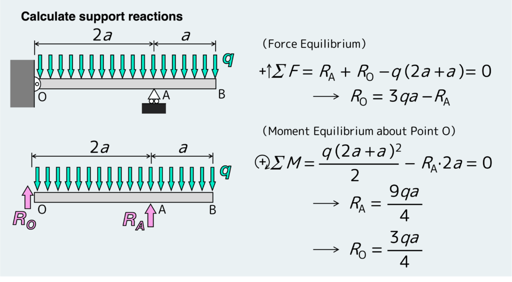
Once you have the support reactions, divide the beam into sections and use the equilibrium equations for each section to find the internal shear force F and bending moment M.
With distributed load problems, the key is to replace the distributed load with an equivalent point load when setting up the equilibrium equations.
In other words, when you write the equilibrium equations for a free body like the one shown below, treat the distributed load as a single point load of “qx” acting at the center of that loaded length—that is, at a position “x/2” from either end of the free body.
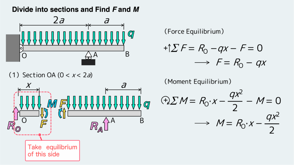
For Section AB, you can find F and M in the same way.
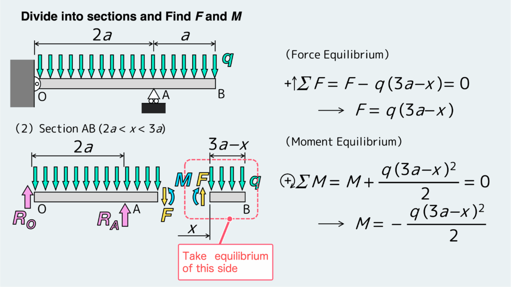
In distributed load problems, the equation for F becomes a linear function of x, and the equation for M becomes a quadratic function of x. That makes the expressions a bit more complicated than in other examples, so be careful not to make calculation mistakes.
If you plot the resulting F and M, the diagrams look like this:
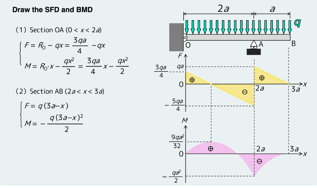
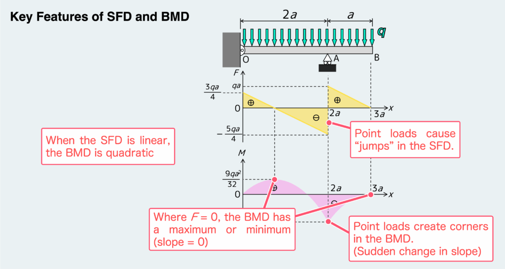
Because the expression for M is quadratic, the BMD takes the shape of a parabola, as shown in the figure. One important warning here: don’t just sketch the parabolic BMD carelessly without checking the key relationships.
The graph should reflect the fact that the slope of the BMD at any point is equal to the value of F at that same point.
A simple example is the point where F = 0. At that location, the slope of the BMD—that is, the slope of the tangent to the quadratic curve—must also be zero. So the graph must have a maximum or minimum there. Keep points like this in mind when drawing the graph.
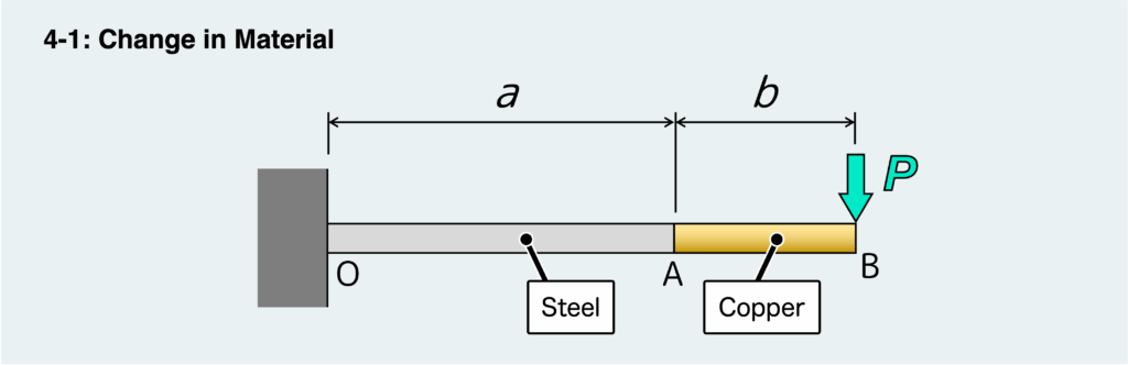
Sometimes, you may come across problems where the material of the beam changes partway along its length.
Sounds like it might get complicated, right? Or maybe not?
Let’s look at the answer together with the next case—when the cross-sectional shape and dimensions change.
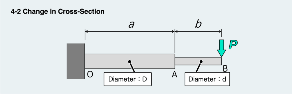
You might also encounter problems where the cross-sectional shape or dimensions of the beam change along its length.
So, what happens in that case?
To be honest, problems like these—along with the previous case of changing material—are nothing to worry about. They’re essentially trick questions.
Here’s the key takeaway: when drawing SFDs and BMDs, you don’t need to worry at all about changes in material or cross-section.
Why? Because SFDs and BMDs deal with the internal forces transmitted through the beam.
No matter how the material changes or how the cross-section varies, the internal forces themselves remain the same.
Material properties come into play when discussing deformation and failure. Meanwhile, cross-sectional shape affects stress (and therefore also influences deformation and failure).
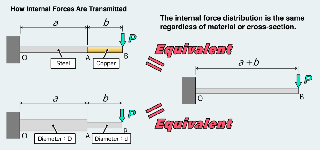
In other words, if you’re only interested in SFDs and BMDs, a problem like this can be treated exactly the same as a cantilever beam of length “a + b” subjected to a point load P at its tip.
So, you can simply solve the problem without worrying about changes in material or cross-sectional geometry.
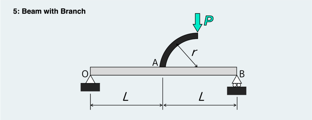
Finally, let’s look at a beam with a branch attached to it. In the example above, the beam branches off at point A, the midpoint of the main beam, and a load P acts at the tip of that branch. Here, we will treat the branch as a rigid body—though honestly, it does not have to be rigid for this discussion. The point is that we are only interested in the SFD and BMD of beam OB.
There is more than one way to approach this kind of problem, but personally, I think the best way is not to worry too much about the branch itself and just work through it in the usual way.
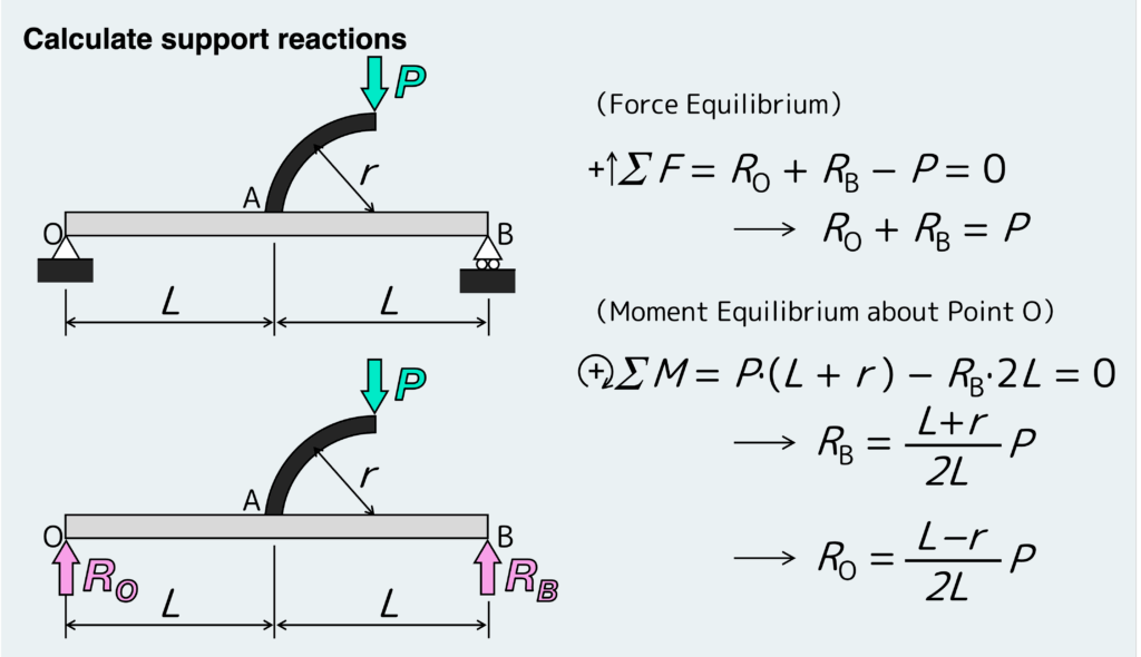
So, let’s follow the same procedure as always. First, find the support reactions.
As usual, determine the reactions by isolating the entire beam as a free body—including the branch—and then applying the equilibrium equations.
Next, divide the beam into sections and use the equilibrium equations to find the internal shear force F and bending moment M for each section.
For problems with a branch, the natural place to divide the beam is at the branching point.
Let’s start with Section OA—the region to the left of the branch.
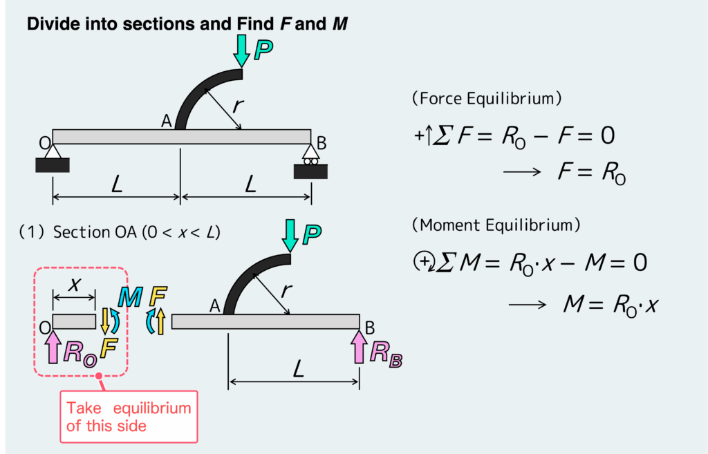
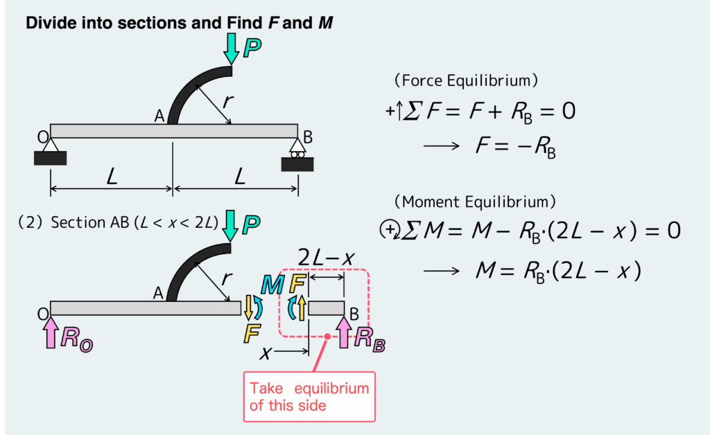
Next, let’s look at Section AB—the region to the right of the branch.
In both sections, it is usually easier to apply the equilibrium equations to the free body that does not include the branch.
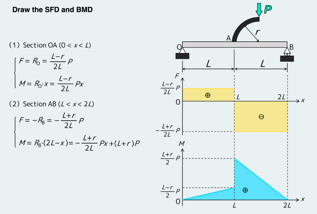
Once you have found F and M for each section, draw the SFD and BMD.
A lot of people probably find this less complicated than expected, despite the presence of the branch. In fact, some readers may wonder whether this approach really accounts for the branch at all, since in both sections we applied the equilibrium equations to a free body that does not include the branch.
But there is no need to worry about that. The effect of the branch has already been taken into account when we determined the support reactions RO and RB at the start.
So yes—the influence of the branch is fully included in RO and RB.
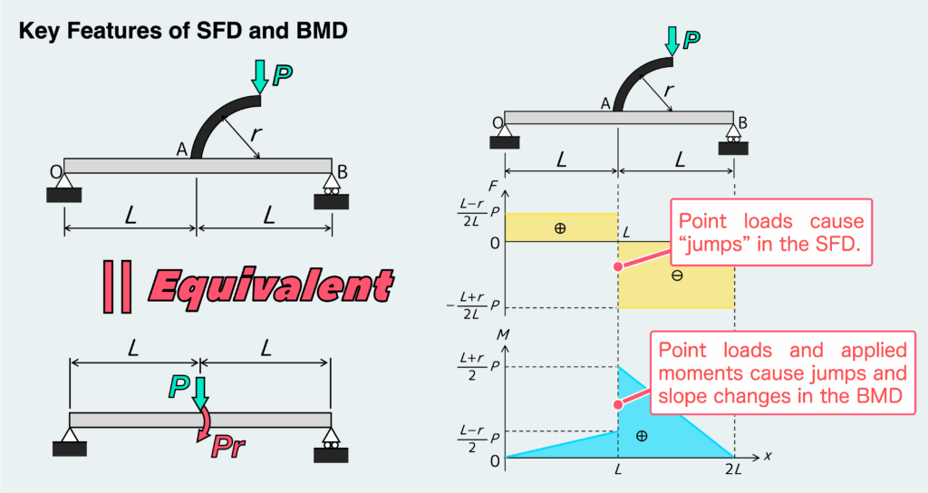
Finally, let’s review the key features that appear in the SFD and BMD.
Problems like this are essentially equivalent to a case where a point load and a moment act at the base of the branch, as shown in the figure below. As a result, the SFD and BMD show the corresponding features of that equivalent loading.
We’ve gone through six different examples to understand SFDs and BMDs in detail—how did it feel?
If even one of these examples helped you, that’s a win 👍
Across these four articles, we’ve taken a deep dive into SFDs and BMDs. They are absolutely fundamental when dealing with bending problems. Without a solid understanding here, it’s difficult to move on to topics like stress, deformation, and failure.
If you’re still not fully confident, I’d recommend going back and reviewing all four articles—including this one—carefully.
In the next article, we’ll move on to stress due to bending.
How to Draw SFD & BMD: Worked Example and Step-by-Step Solution
How Different Loads Appear in Shear Force and Bending Moment Diagrams (SFD and BMD)
How to Draw Shear Force and Bending Moment Diagrams (SFD & BMD) Step by Step
Shear Force Diagram & Bending Moment Diagram (SFD/BMD): What They Are and Why They Matter
- If you follow the step-by-step procedure, you’ll be able to draw SFD and BMD correctly for any problem.
- You’ll understand the key characteristics that appear in SFD and BMD—and learn to check whether your diagrams properly reflect them.
- Changes in material or cross-sectional shape do not need to be considered when simply drawing SFD and BMD.
渾身のnoteを書きました!!
「公式は覚えてるのに問題を見たら手が止まる…」
そんなあなたは『解法の型・流れ』を理解できていないのです。材料力学は色々な問題がありますが、実は決まった型に沿って解くことができ、この型こそが材力の基礎であり極意であると言えます。
このnote記事は、本ブログ管理人のぽるこが「材料力学の問題を解く上での型・要点・コツ」を本気でまとめあげました。かなりの大ボリュームかつエッセンスを詰め込んだものですが、1,200円という映画1本分にも満たない価格設定としました。
本ブログに書ききれていない内容も多く含んでおりますので、ぜひ読んでみてください!