

What is stress? Still not quite getting it?
A lot of people struggle with this concept at first—and that’s totally normal.
After all, stress isn’t something you really learn in high school physics, so it doesn’t always click right away.
But in Strength of Materials, understanding stress is absolutely essential.
You could even say that mastering stress is the key to mastering the entire subject.
In this article, I’ll explain stress in the simplest way possible.
If you’ve been studying Strength of Materials but still feel stuck, stick with me until the end.
In just 10 minutes, you’ll have a solid grasp of the fundamentals—and be ready to take the next step.
- What Strength of Materials is really about
→ Understanding how forces are transmitted through objects, and how that leads to deformation or failure. - What stress actually means
→ A measure of how much load a material experiences, taking its size and shape into account. - Why stress matters
→ It determines how much a material deforms and whether it will fail. - Types of stress
→ Normal stress (tensile and compressive) and shear stress, depending on the type of internal force. - How to calculate different types of stress properly
→ You need to understand stress distributions and calculation methods for each type of loading.
渾身のnoteを書きました!!

「公式は覚えてるのに問題を見たら手が止まる…」
そんなあなたは『解法の型・流れ』を理解できていないのです。材料力学は色々な問題がありますが、実は決まった型に沿って解くことができ、この型こそが材力の基礎であり極意であると言えます。
このnote記事は、本ブログ管理人のぽるこが「材料力学の問題を解く上での型・要点・コツ」を本気でまとめあげました。かなりの大ボリュームかつエッセンスを詰め込んだものですが、1,200円という映画1本分にも満たない価格設定としました。
本ブログに書ききれていない内容も多く含んでおりますので、ぜひ読んでみてください!
If you’re studying Strength of Materials, you might be wondering:
What is this subject actually for? And how do we use it?
A simple way to answer that question is this:
The first part of that definition—how forces are transmitted—requires a solid understanding of free body diagrams.
I’ve explained this concept in detail in another article, so if you’re not fully comfortable with it yet, definitely check that out.
![[thumbnail]_Vol1-2-3en](https://secondinspire.com/wp-content/uploads/thumbnail_Vol1-2-3en-min-160x160.png)
The concept of the free body_Truss (vol.1-2-3)
![[thumbnail]_Vol1-2-2en](https://secondinspire.com/wp-content/uploads/thumbnail_Vol1-2-2en-min-160x160.png)
The concept of the free body_Types of support (vol.1-2-2)
![[thumbnail]_Vol1-2-1en](https://secondinspire.com/wp-content/uploads/thumbnail_Vol1-2-1en-min-160x160.png)
The concept of the free body (vol.1-2-1)
![[thumbnail]_Vol1-1en](https://secondinspire.com/wp-content/uploads/thumbnail_Vol1-1en-min-160x160.png)
The concept of the free body (vol.1-1)
Now, the second part—deformation and failure—is where stress comes in.
To understand how a material deforms or breaks, we need a way to measure how much load it is actually experiencing.
That’s exactly what stress represents.
As stress increases, materials deform more.
And if the stress exceeds the material’s limit, failure occurs.
So if you want to prevent failure, you must design structures so that the stress stays below that limit.
In other words, deformation and failure are largely governed by stress.
That’s why understanding stress properly is one of the main goals in Strength of Materials.
So in this article, let’s break it down step by step.
Stress is a way to describe how much load a material is experiencing when a force is applied to it.
At first glance, you might think:
“If we want to know how heavily a material is loaded, isn’t it enough to just look at the force?”
But it’s not that simple.
Take a look at this example.
Imagine two solid steel rods:
- one with a diameter of 10 cm
- the other with a diameter of 5 mm
Now hang a 1-ton car from each rod.
The force applied to both rods is the same—about 1000 kgf (10,000 N).
But clearly, the thinner rod is under much more severe conditions.
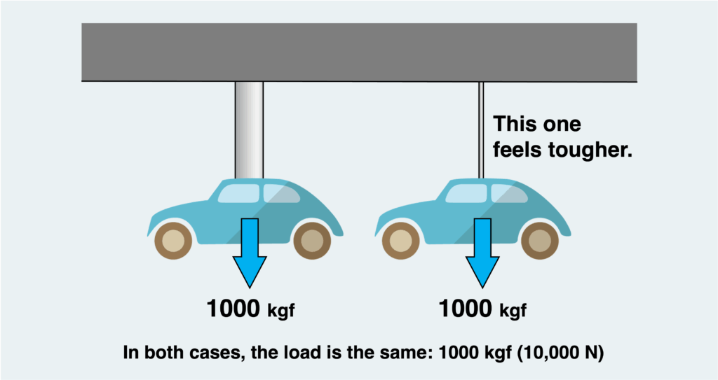
Even when the applied force is the same, how “hard” a material is being pushed can be completely different.
To evaluate this properly, we need more than just force.
We need a measure that also takes into account the size and cross-sectional shape of the material.
That measure is stress.
In other words, stress allows us to compare how severely different materials are loaded—even if their sizes and shapes are different.
In the simplest case, stress is calculated by dividing the internal force acting on a cross section by its area.
In more technical terms, stress is the magnitude of internal force per unit area.
(For simplicity, we assume that the internal force is uniformly distributed over the cross section. In cases such as bending or torsion—or when considering Saint-Venant’s principle—stress cannot always be obtained by simply dividing force by area.)
You might be wondering:
“Wait, what exactly is internal force?”
That’s a key concept for understanding stress—and it’s absolutely essential.
We’ll go over it in detail in the next section.
Also, as we’ll see later, there are two main types of stress:
- Normal stress (σ, sigma)
- Shear stress (τ, tau)
The unit of stress is force divided by area, such as N/m² or kgf/mm²,
but the most commonly used unit is MPa, which is equivalent to N/mm².
What determines the stress at any point inside a material is the internal force.
So if you want to understand stress, you first need to understand internal forces.
Let’s start by clearly distinguishing between external forces and internal forces.
- External Force: A force applied from outside the structure. In textbook practice questions, these are the forces given in the figure.
- Internal Force: A force that develops inside the structure as a result of external forces. You can’t see it at first—it only becomes visible when you draw a free body diagram.
Instead of just explaining this in words, it’s much easier to understand with an example.
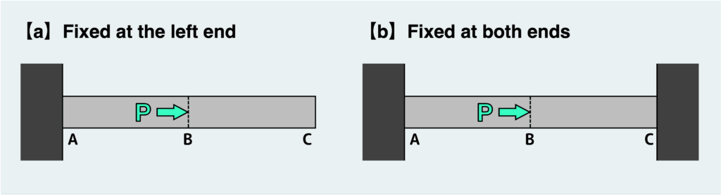
Consider a bar labeled AC, as shown in the figure below.
A load P is applied at point B, which is located at the midpoint of the bar.
This load P is what we call an external force.
Now, let’s look at two different cases:
- Case (a): The bar is fixed only on the left end
- Case (b): The bar is fixed at both ends
For each case, we’ll examine the internal forces and the resulting stress in the material.
To understand how forces are transmitted inside a material—in other words, to determine the internal forces—we need to cut the material virtually and isolate a part of it as a free body.
Only after making this cut can we draw the internal forces acting on the cross-section.
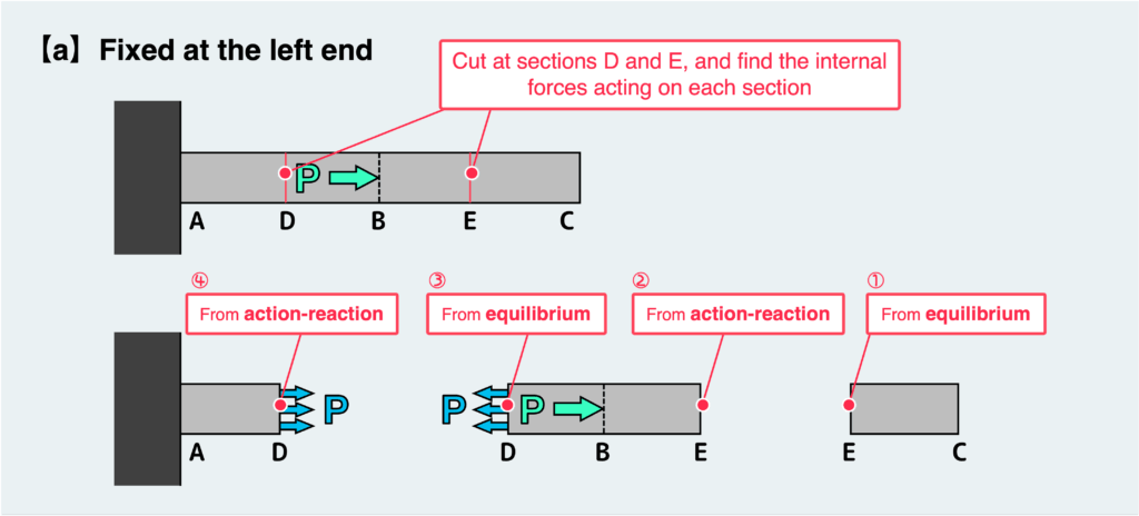
To find the internal forces in segments AB and BC, let’s make a cut somewhere within each segment and draw the corresponding free body diagrams.
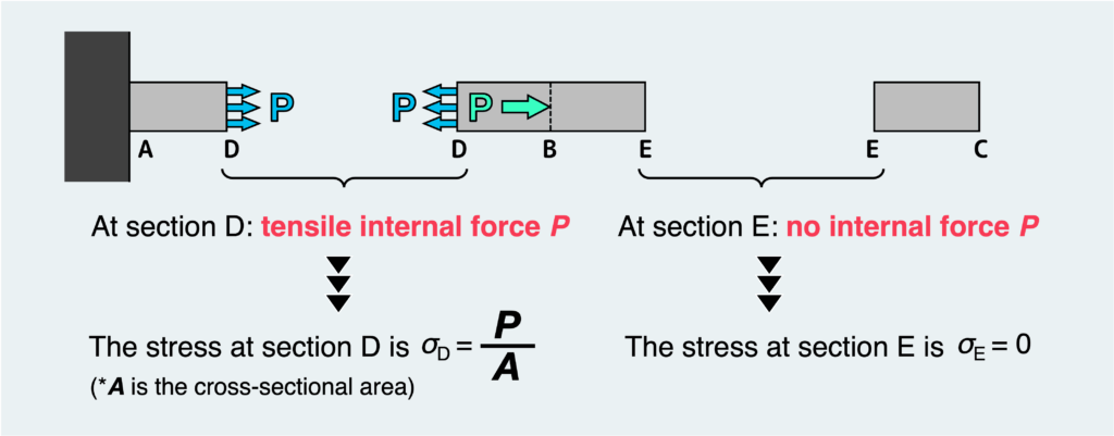
First, consider case (a).
Using the equilibrium conditions and Newton’s third law, we can determine the internal forces acting on the cut surface, as shown in the figure.
(The steps labeled ①–④ in the diagram illustrate the reasoning process.)
Although the diagram shows a cut at a specific location, the result does not change even if we cut at a different point within the same segment.
This means:
- In segment AB, a tensile internal force P acts at every cross section
- In segment BC, no internal force acts anywhere
Once we know the internal forces, we can determine the stress at each location.
In segment AB, where the internal force P is transmitted, every cross section experiences a tensile stress of P/A.
On the other hand, in segment BC, no internal force acts—so there is no stress anywhere in that segment.
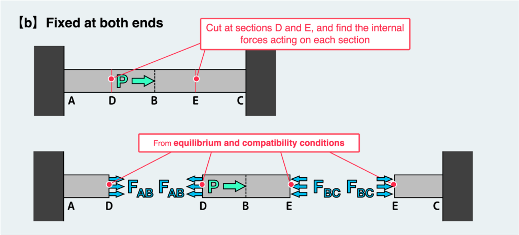
Now, let’s move on to case (b).
The approach is the same: we cut the bar somewhere within AB and BC, and draw the corresponding free body diagrams.
In this case, however, the internal forces cannot be determined from equilibrium conditions alone—this is a statically indeterminate problem.
For now, let’s set that aside.
Suppose that, using both equilibrium and deformation conditions, the internal forces in segments AB and BC are determined as shown in the figure.
Then:
- In segment AB, a tensile internal force FAB acts, so each cross section experiences a tensile stress of FAB/A
- In segment BC, a compressive internal force FBC acts, so each cross section experiences a compressive stress of FBC/A
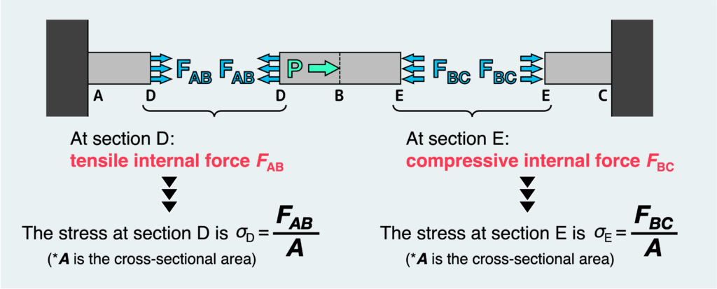
In both cases, the externally applied force is the same (P).
However, because the boundary conditions are different, the internal forces—and therefore the stresses—are different in each segment.
In other words, the stress at any point is determined by the internal force at that location.
Now that we have a rough idea of what stress is, let’s look at how it’s actually used. In practice, stress is mainly used for:
- designing safe structures
- judging whether a structure is safe or at risk of failure
The idea is simple. We compare the stress acting on a material with the material’s strength limit.
- If the stress exceeds the limit → failure
- If the stress stays below the limit → safe
That’s all there is to it.
As explained earlier, the stress in a material can be calculated from the internal forces.
For example, consider a bar under a tensile load.
The internal force is equal to the applied force, so the stress can be obtained by dividing that force by the cross-sectional area.
On the other hand, the strength limit of a material depends on the material itself and is typically defined by standards.
There are several types of limits, and which one you should use depends on what kind of behavior is acceptable—and what is not.
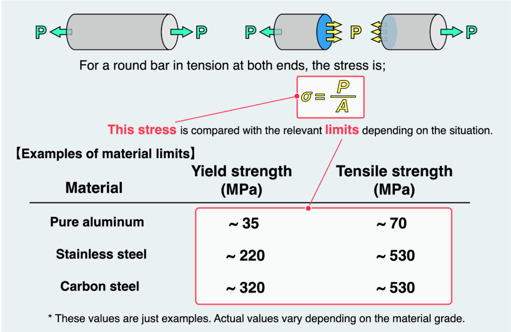
If all you care about is preventing fracture, you can simply design so that the stress does not exceed the ultimate tensile strength.
However, in many cases, even large deformation is not acceptable—which is usually the case in real applications.
In such situations, you need to use the yield stress (or proof stress) as the limit instead.
In practice, we don’t design structures right at their limits.
Instead, we apply a safety factor and set an allowable stress that is much lower than the material’s strength.
(Strictly speaking, if a structure is subjected to repeated loading over a long period, fatigue must also be considered.
However, that would make things much more complicated, so we’ll ignore fatigue for now.)
So, what does “safe design” actually mean?
In simple terms, it comes down to the following:
- Reduce stress by minimizing internal forces through better structural design
- Reduce stress by increasing dimensions (e.g., cross-sectional area)
- Increase allowable stress by selecting stronger materials
These are the basic directions for safe design.
However, in reality, there are always constraints—such as limits on size, manufacturing difficulty with high-strength materials, cost reduction requirements, and sometimes even aesthetics.
Balancing safety with these constraints—that’s the real job of an engineer.
As mentioned earlier, there are two main types of stress:
- Normal stress
- Shear stress
Normal stress can be further divided into:
- Compressive stress
- Tensile stress
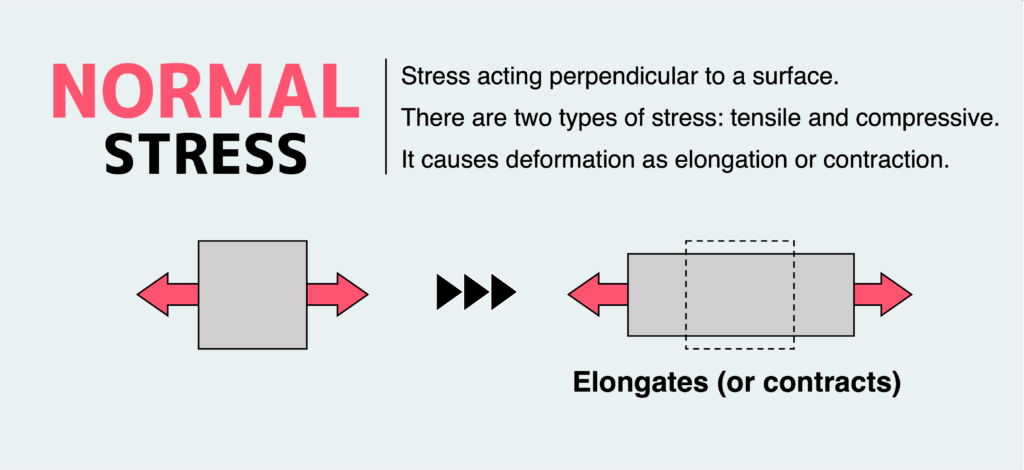
Normal stress acts perpendicular to a cross section.
It causes deformation in the form of elongation (stretching) or contraction (shortening).
Normal stress is denoted by σ (sigma), and its unit is typically MPa.
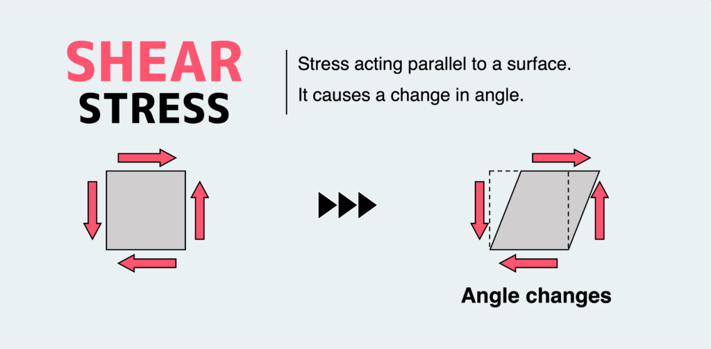
Shear stress acts parallel to a cross section.
It causes deformation as a change in angle (shear deformation).
Shear stress is denoted by τ (tau), and its unit is also MPa.
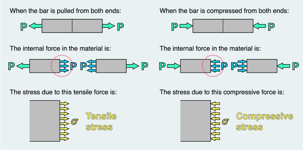
Normal stress is generated by internal forces acting perpendicular to a cross section.
- If the internal force is tensile, the stress is tensile stress
- If the internal force is compressive, the stress is compressive stress
As a result of normal stress, a material deforms by stretching or shortening in that direction.
In everyday life, when we think of “force,” we usually mean forces acting perpendicular to a surface—so normal stress is relatively easy to visualize.
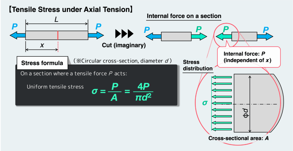
Now, consider a material subjected to a tensile load.
At any cross section inside the material, an internal tensile force P acts—equal in magnitude to the applied external force, as shown in the figure below.
This results in a uniform tensile stress across the cross-section, and its magnitude can be expressed by the equation shown in the figure below.
When the internal force is a bending moment, the stress acting on a cross section is still normal stress.
However, in this case, it behaves a bit differently—it consists of both tensile and compressive stress.
We’ll cover bending in detail later, but for now, let’s look at a simple example.
In Strength of Materials, bending is often discussed using beams.
A beam is a structural member that extends horizontally,
while a vertical member is typically called a column.
As a simple example, consider a cantilever beam subjected to a load at its free end.
At any cross section along the beam, internal forces such as shear force and bending moment act.
(Strictly speaking, shear force also produces shear stress on the cross section. However, in many bending problems, shear stress is much smaller than the stress caused by bending moments, so we will ignore it here for simplicity.)
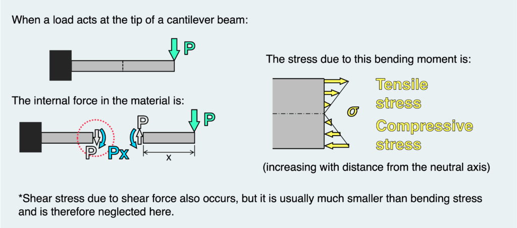
So, what does the stress distribution look like under bending?
- The upper half experiences tensile stress
- The lower half experiences compressive stress
More precisely:
- The stress at the center (neutral axis) is zero
- The farther you move away from the center, the larger the stress becomes
You can actually get a feel for this by bending something with your hands.
The top side tries to stretch, while the bottom side tries to compress.
And the farther from the center you go, the more pronounced this deformation becomes.
This type of stress distribution—where tensile and compressive stresses coexist due to bending—is called bending stress.
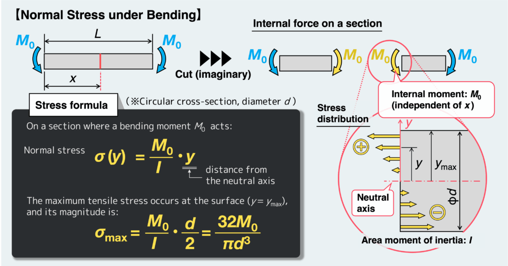
To calculate the magnitude of bending stress, we use the bending moment M₀ acting on the cross section.
Specifically, we divide M₀ by the Area Moment of Inertia I, and then multiply it by the distance y from the neutral axis, as shown in the figure above.
When evaluating the safety of a material, the most important value is usually the maximum stress.
To find this maximum bending stress, we use the maximum value of y—that is, the distance from the neutral axis to the outer surface of the material, ymax.
This means that the maximum stress occurs at the surface of the material.
You’ve probably experienced this yourself—when you bend something like an eraser, cracks tend to start from the surface.
This happens because the maximum bending stress develops at the surface.
Shear stress can feel a bit harder to grasp at first.
Just like tensile and compressive stress are caused by internal forces acting perpendicular to a cross section, shear stress is caused by internal forces acting parallel to a cross section—which we call shear force.
A shear force acts along a surface, and naturally, the resulting shear stress also acts along that surface.
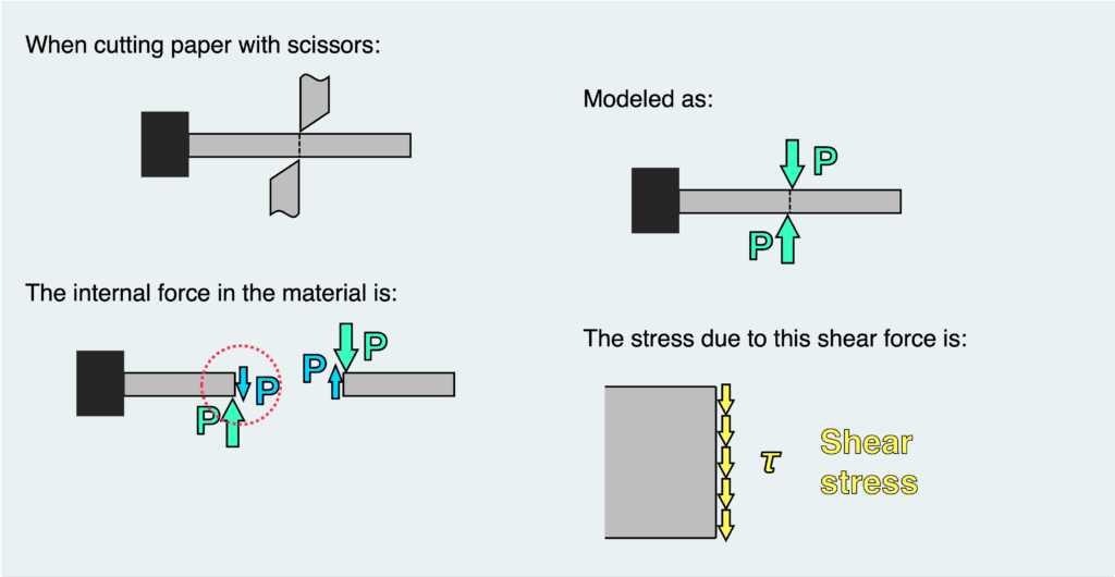
A very familiar example of shear force and shear stress is cutting paper with scissors.
If we model this situation, as shown in the figure, the surface where the paper is being cut—between the two blades—experiences stress acting along that surface.
That stress is shear stress.
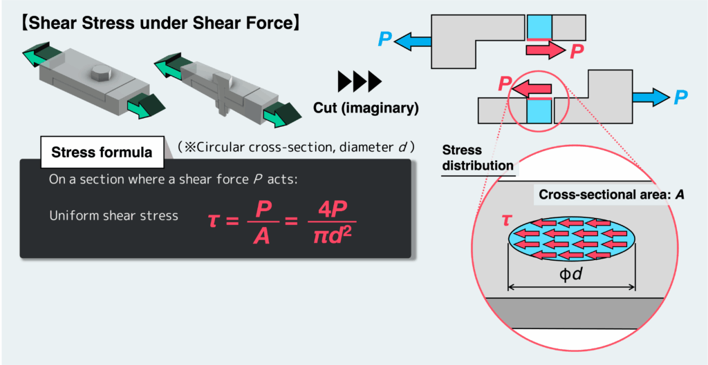
A more engineering-oriented example would be rivets, pins, or bolts used to connect structural members.
These components are also subjected to shear stress.
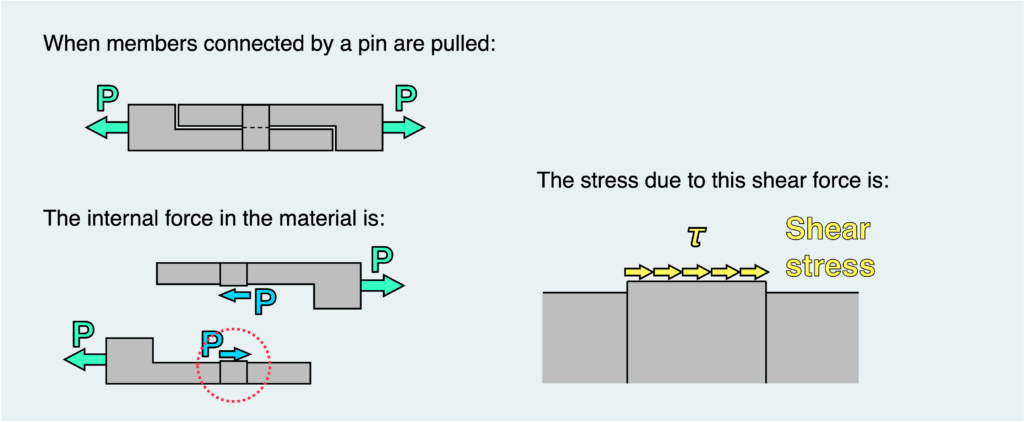
When materials are joined using pins, rivets, or bolts, the shear stress acting on the cross section can be understood as shown in the figure.
Just like in the case of tension, we typically assume that the shear stress is uniformly distributed over the cross section.
Therefore, the shear stress can be calculated by dividing the shear force P acting on the cross section by its area: τ = P/A.
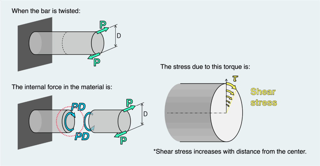
Another important case where shear stress appears is torsion.
For a shaft subjected to twisting, the internal force acting on the cross section is a torsional moment (torque).
The shear stress caused by torque has a non-uniform distribution, similar to bending.
In the same way as bending:
- The center of the material does not deform
- The outer region tends to deform more
As a result:
- The shear stress at the center is zero
- The stress increases as you move away from the center
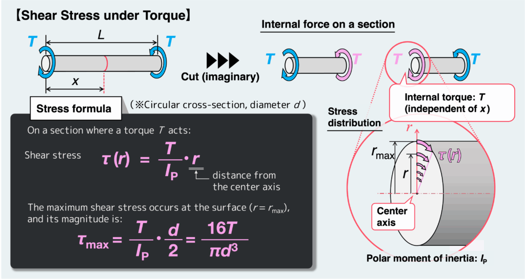
To calculate this shear stress, we use the torque T acting on the cross section.
We divide T by the polar moment of inertia IP, and multiply it by the distance r from the center axis.
You can see that this has almost the same form as the bending stress equation.
Just like in bending, the maximum shear stress occurs at the surface of the material.
Its value is obtained by using the maximum value of r—that is, the distance from the center to the outer surface.
I’ve tried to explain stress in the simplest and most intuitive way possible—how was it?
If this helped you get even a basic understanding of stress, which is essential for mastering Strength of Materials, then I’m glad.
- What Strength of Materials is really about
→ Understanding how forces are transmitted through objects, and how that leads to deformation or failure. - What stress actually means
→ A measure of how much load a material experiences, taking its size and shape into account. - Why stress matters
→ It determines how much a material deforms and whether it will fail. - Types of stress
→ Normal stress (tensile and compressive) and shear stress, depending on the type of internal force. - How to calculate different types of stress properly
→ You need to understand stress distributions and calculation methods for each type of loading.
渾身のnoteを書きました!!
「公式は覚えてるのに問題を見たら手が止まる…」
そんなあなたは『解法の型・流れ』を理解できていないのです。材料力学は色々な問題がありますが、実は決まった型に沿って解くことができ、この型こそが材力の基礎であり極意であると言えます。
このnote記事は、本ブログ管理人のぽるこが「材料力学の問題を解く上での型・要点・コツ」を本気でまとめあげました。かなりの大ボリュームかつエッセンスを詰め込んだものですが、1,200円という映画1本分にも満たない価格設定としました。
本ブログに書ききれていない内容も多く含んでおりますので、ぜひ読んでみてください!