
![[thumbnail]_Vol1-2-1en](https://secondinspire.com/wp-content/uploads/thumbnail_Vol1-2-1en-min-940x529.png)

In the previous article, I covered the basics of the free body concept and its application. Over the next few articles, we’ll explore various problem patterns to further enhance your proficiency in using the free body.
I’ll present a total of five examples. Since this will be a lengthy article, feel free to focus on the sections that interest you the most. However, if you’re up for it, reading through all the examples will help deepen your understanding.
In this article, I’ll explain about [bars under tension and compression].
Other examples (some of which are still being written) are as follows.
![[thumbnail]_Vol1-2-2en](https://secondinspire.com/wp-content/uploads/thumbnail_Vol1-2-2en-min-160x160.png) The concept of the free body_Types of support (vol.1-2-2)
The concept of the free body_Types of support (vol.1-2-2)
![[thumbnail]_Vol1-2-3en](https://secondinspire.com/wp-content/uploads/thumbnail_Vol1-2-3en-min-160x160.png) The concept of the free body_Truss (vol.1-2-3)
The concept of the free body_Truss (vol.1-2-3)
If you’re interested in learning the basics of free body, please refer to the article below.
![[thumbnail]_Vol1-1en](https://secondinspire.com/wp-content/uploads/thumbnail_Vol1-1en-min-160x160.png) The concept of the free body (vol.1-1)
The concept of the free body (vol.1-1)
- Internal forces are always represented within the cross section after the free body is cut out.
- A uniform internal force in tension or compression is exerted at any cross section in a material subjected to simple tension or compression.
- A material subjected to multiple tensile and compressive forces can be regarded as a superposition of materials subjected to simple single tensile and compressive forces.
- Understanding how internal forces are transmitted within a material is the initial step in comprehending the stresses and deformations of the material.
渾身のnoteを書きました!!
「公式は覚えてるのに問題を見たら手が止まる…」
そんなあなたは『解法の型・流れ』を理解できていないのです。材料力学は色々な問題がありますが、実は決まった型に沿って解くことができ、この型こそが材力の基礎であり極意であると言えます。
このnote記事は、本ブログ管理人のぽるこが「材料力学の問題を解く上での型・要点・コツ」を本気でまとめあげました。かなりの大ボリュームかつエッセンスを詰め込んだものですが、1,200円という映画1本分にも満たない価格設定としました。
本ブログに書ききれていない内容も多く含んでおりますので、ぜひ読んでみてください!
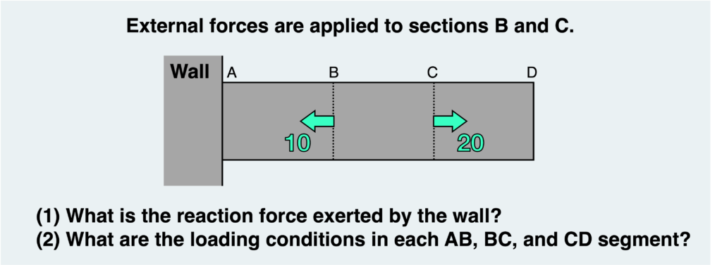
In this article, let’s delve into drawing a fundamental free body diagram by addressing the following “bar under tension and compression” problem.
As shown in the figure, external forces are applied to points in the middle of a bar connected to a wall on one end. In this scenario, we’ll examine (1) the reaction force exerted by the wall and (2) the loading conditions in each segment of AB, BC, and CD.
Let’s first consider the reaction force exerted by the wall at section A.
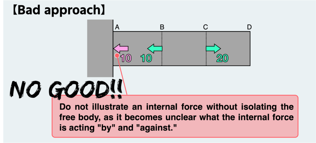
Since the reaction force is also a type of internal force, it remains invisible until we isolate the free body. Therefore, it’s not acceptable to depict the reaction force without isolating the free body, as illustrated in the figure above.
Indeed, the depicted forces seem to balance each other. However, there’s a serious problem with this approach. It’s not clear what the internal force is applied “by” and “against” in this depiction.
This approach will undoubtedly lead to confusion, especially when dealing with more challenging problems, and it must be changed accordingly.
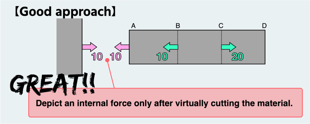
To be accurate, the material must be cut at the location where the internal force is to be determined (in this case, at section A connected to the wall, since we’re interested in the reaction force). Then, the internal force must be depicted on this cut surface, as illustrated in the figure above.
This is the fundamental principle. Many individuals mistakenly believe they’ve created a free body diagram without actually cutting the material, so if you find yourself in that situation, it’s crucial to revisit the fundamentals.
Next, let’s examine the loading conditions inside this material. Initially, let’s make a cut somewhere along segment BC and examine the internal force transmitted across this cross-section.
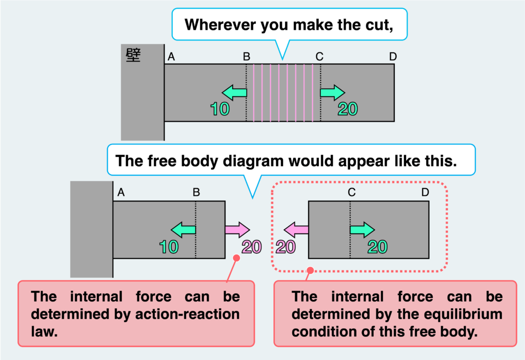
You’ll notice that regardless of where you make the cut between BC, the resultant free body diagram remains essentially the same. In other words, the internal force acting on the section will always be a tensile load of “20,” regardless of the cut’s location between BC.
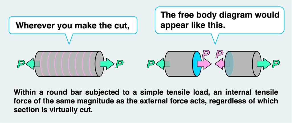
Let’s revisit what was discussed in the previous article. A bar with a tensile load P at both ends experiences a uniform tensile internal force (of the same magnitude as the external force) extending from one end to the other. Similarly, a constant tensile load is transmitted throughout segment BC, spanning from one end to the other.
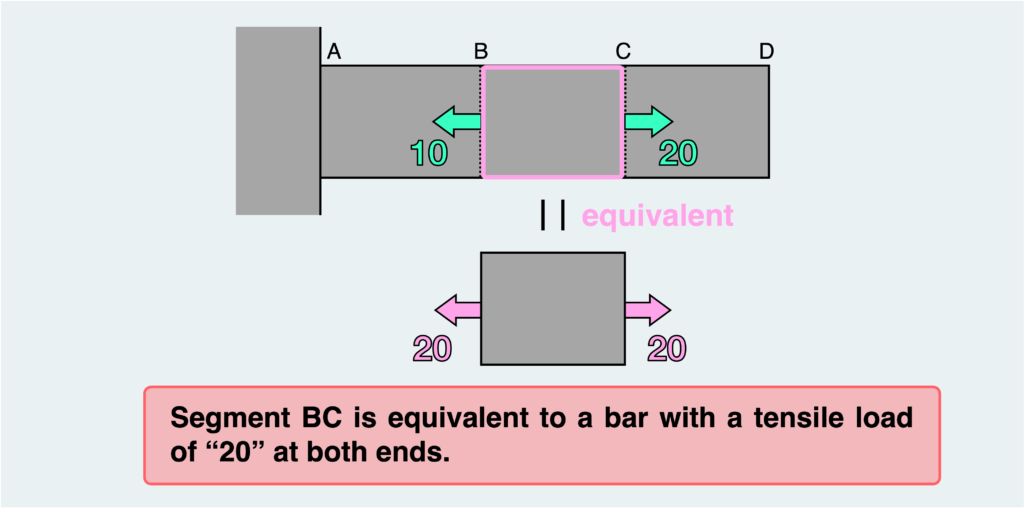
In essence, segment BC can be likened to a bar with a tensile load of “20” at both ends.
Now, let’s contemplate the nature of the internal force transmitted between AB and CD.
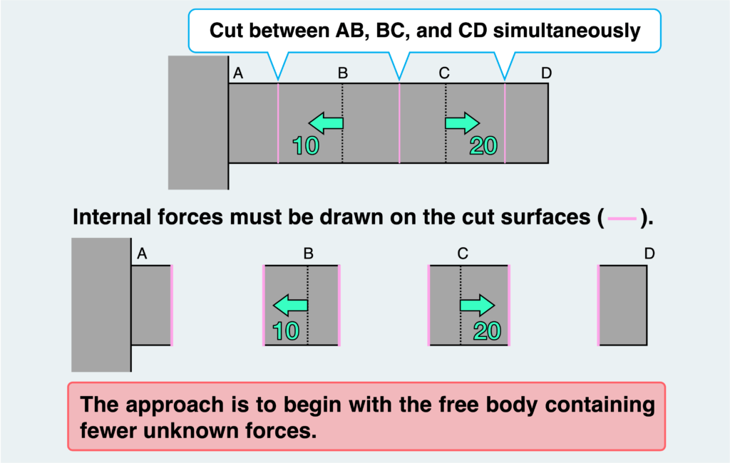
This time, we’ll depict free-body diagrams by cutting between AB, BC, and CD simultaneously, resulting in multiple free bodies. The internal forces within these free bodies must exist to satisfy the equilibrium condition. When dealing with the equilibrium of multiple free bodies like this, the approach is to begin with the free body containing fewer unknown forces.
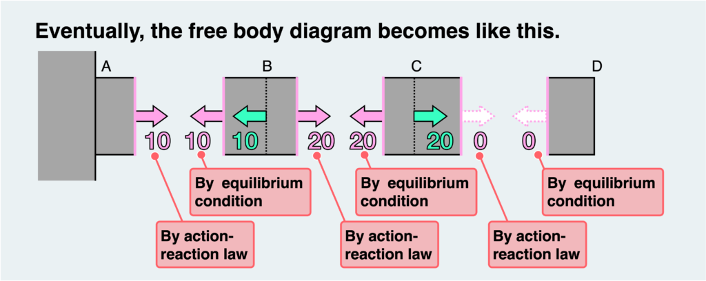
In this problem, we’ll commence with the rightmost free body. From there, we’ll sequentially determine the unknown internal forces, utilizing the equilibrium condition and the principles of action and reaction, as illustrated in the figure above.
Similar to when considering the internal force in segment BC, the internal force transmitted there remains constant regardless of the cut’s position between AB and CD. In other words, a uniform tensile load of “10” exists between AB, while there’s no load present between CD.
Using the same reasoning applied to segment BC, we can conclude that segment AB is equivalent to a bar under tension “10” at both ends, while segment CD resembles an unloaded bar.
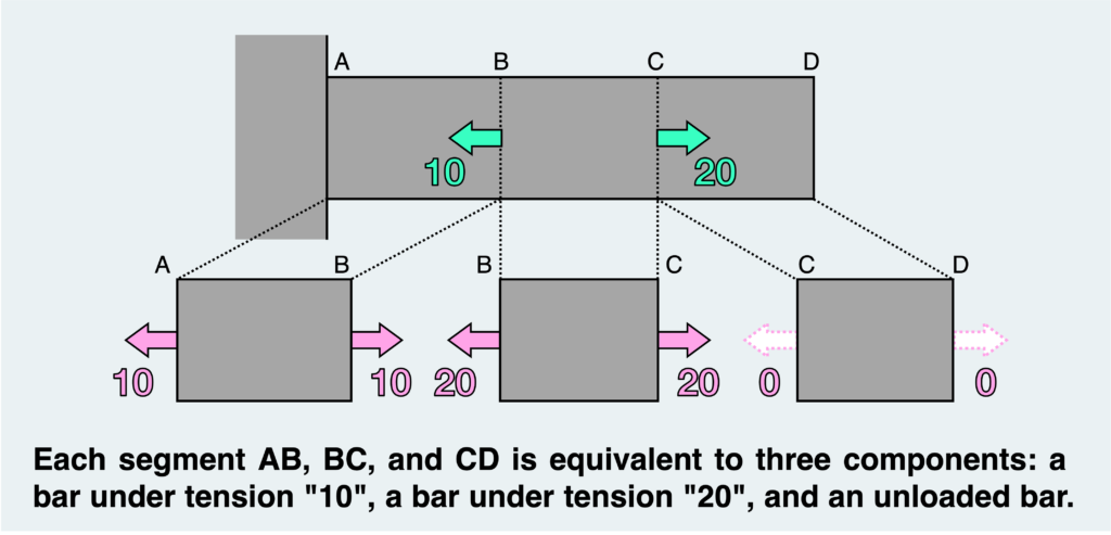
In summary, this structure comprises three components: a bar under tension “10”, a bar under tension “20”, and an unloaded bar.
The initial step in the mechanics of materials is to accurately understand “the nature of internal forces transmitted within a material.” Once this is accomplished, you can proceed to the subsequent step, which involves calculating the magnitude of stress and deformation (elongation and contraction) experienced by each component.
I believe the explanation above should suffice, but some may still find it somewhat unclear. For those who do, here’s a more direct explanation.
Now, we aim to determine the type of load (internal force) experienced by segments AB, BC, and CD. To do this, let’s isolate segments AB, BC, and CD as free bodies as they are.
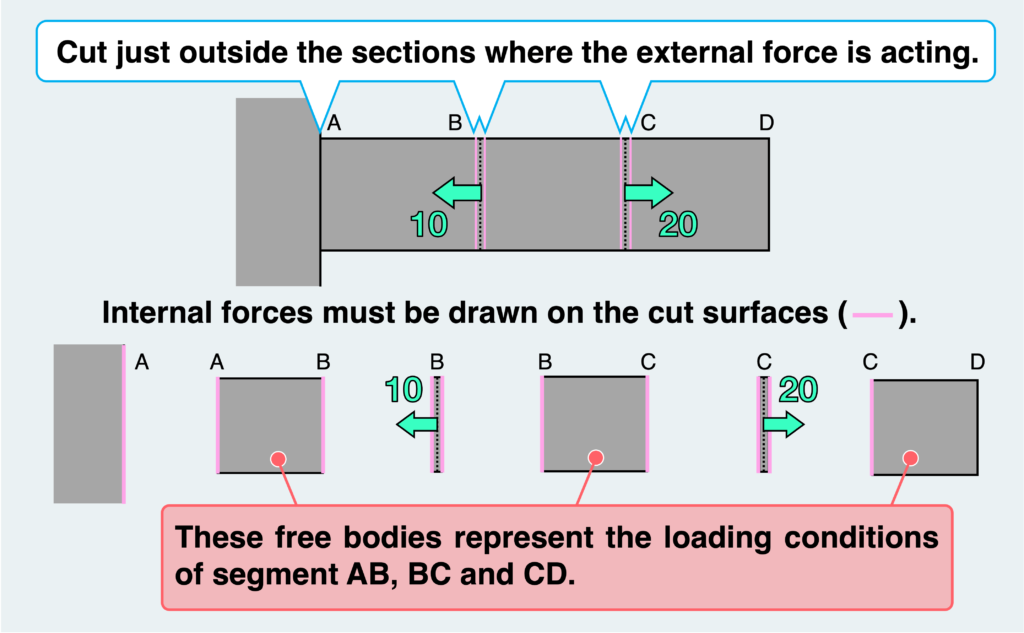
You may be tempted to cut just at the section B or C, but then you may be confused about where to draw the external force. Therefore, let’s consider cutting just outside the sections where the external force is acting, so as not to include the external force.
Then, as shown in the figure above, we can isolate AB, BC, CD, and two thinly filmed free bodies that include external forces, for a total of 5 free bodies.
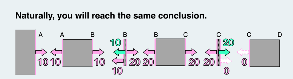
Then, once more, we can determine the internal forces using the equilibrium condition and the law of action-reaction, starting from the rightmost free body. This will lead to the same conclusion as explained above (naturally).
By contemplating this fundamental problem, you should now have a grasp of how to approach and depict free body diagrams.
Once more, I cannot stress enough how crucial this is, so I’ll reiterate the following points. Please ensure you understand them thoroughly before moving on to other examples. Once you’ve mastered all of them, you’ll have a solid understanding of the key principles of mechanics of materials.
- Internal forces are always represented within the cross section after the free body is cut out.
- A uniform internal force in tension or compression is exerted at any cross section in a material subjected to simple tension or compression.
- A material subjected to multiple tensile and compressive forces can be regarded as a superposition of materials subjected to simple single tensile and compressive forces.
- Understanding how internal forces are transmitted within a material is the initial step in comprehending the stresses and deformations of the material.
渾身のnoteを書きました!!
「公式は覚えてるのに問題を見たら手が止まる…」
そんなあなたは『解法の型・流れ』を理解できていないのです。材料力学は色々な問題がありますが、実は決まった型に沿って解くことができ、この型こそが材力の基礎であり極意であると言えます。
このnote記事は、本ブログ管理人のぽるこが「材料力学の問題を解く上での型・要点・コツ」を本気でまとめあげました。かなりの大ボリュームかつエッセンスを詰め込んだものですが、1,200円という映画1本分にも満たない価格設定としました。
本ブログに書ききれていない内容も多く含んでおりますので、ぜひ読んでみてください!