
![[thumbnail]_Vol1-2-3en](https://secondinspire.com/wp-content/uploads/thumbnail_Vol1-2-3en-min-940x529.png)

This article explores the third example of the free-body concept, focusing on a truss problem.
Understanding the free-body concept allows grasping how forces are transmitted within structures. In this article, I’ll provide a brief overview of force transmission in a truss structure.
Other examples (some of which are still being written) will be covered as follows.
![[thumbnail]_Vol1-2-1en](https://secondinspire.com/wp-content/uploads/thumbnail_Vol1-2-1en-min-160x160.png) The concept of the free body (vol.1-2-1)
The concept of the free body (vol.1-2-1)
![[thumbnail]_Vol1-2-2en](https://secondinspire.com/wp-content/uploads/thumbnail_Vol1-2-2en-min-160x160.png) The concept of the free body_Types of support (vol.1-2-2)
The concept of the free body_Types of support (vol.1-2-2)
If you’re interested in learning the basics of free body, please refer to the article below.
![[thumbnail]_Vol1-1en](https://secondinspire.com/wp-content/uploads/thumbnail_Vol1-1en-min-160x160.png) The concept of the free body (vol.1-1)
The concept of the free body (vol.1-1)
- A truss structure is characterized by a series of interconnected triangles, with each member linked to others via pins.
- In truss structures, only axial forces (forces along the longitudinal of the member) are present in each member.
- My recommended analysis procedure involves isolating all joints and members, then determining the forces on each member based on vector equilibrium at the joints.
渾身のnoteを書きました!!
「公式は覚えてるのに問題を見たら手が止まる…」
そんなあなたは『解法の型・流れ』を理解できていないのです。材料力学は色々な問題がありますが、実は決まった型に沿って解くことができ、この型こそが材力の基礎であり極意であると言えます。
このnote記事は、本ブログ管理人のぽるこが「材料力学の問題を解く上での型・要点・コツ」を本気でまとめあげました。かなりの大ボリュームかつエッセンスを詰め込んだものですが、1,200円という映画1本分にも満たない価格設定としました。
本ブログに書ききれていない内容も多く含んでおりますので、ぜひ読んでみてください!

Image by Kanenori from Pixabay
Truss structures are ubiquitous in our surroundings, with bridges being one of the most common examples.
These structures resemble a combination of triangles, where each member is interconnected with others by pins. The triangulated configuration contributes to the strength of the structure.
Understanding truss structures is essential in the mechanics of materials, yet many people may struggle with it. This article provides a brief introduction to the concept of force transmission in truss structures. With a good grasp of its characteristics, understanding becomes less daunting. So, I encourage you to read this article through to the end.
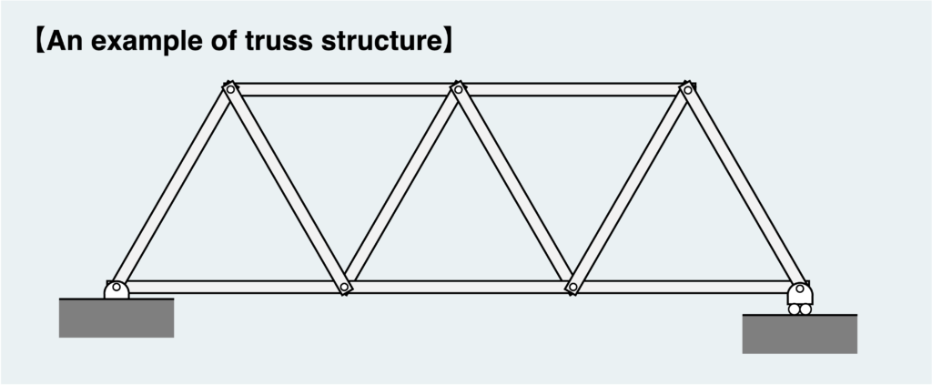
Here’s an example of a typical truss structure. Multiple members are connected by pins to form triangular combinations. The critical aspect of the truss structure is that each member is “pin-connected.”
Because they are connected by pins, they cannot support rotational movement, as explained in the previous article, and therefore cannot transmit moments.
Now, keeping this in mind, let’s consider how force is transmitted to each member.
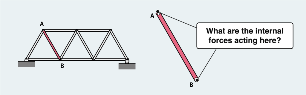
Let’s think about the type of force transmitted to member AB, which has been removed from the truss.
Initially, since this member has been isolated as a free body with points A and B separated, which were originally pin-connected, the sections other than these points A and B are free surfaces, experiencing no internal forces. So, where does the force act?
Naturally, the internal force must act only on points A and B.
There could potentially be two types of forces acting on points A and B: forces aligned with the member’s longitudinal direction and forces perpendicular to this direction (since moments aren’t supported by pins).
The diagram below illustrates these two types of forces acting at both ends of the member. However, as it turns out, this scenario is impossible.
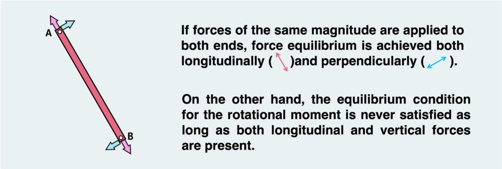
Longitudinal and vertical forces can be balanced. This is because equal magnitude forces in opposite directions should act on points A and B.
However, as long as both longitudinal and vertical forces are present, achieving rotational balance is impossible, no matter how much effort you put in. Because in this scenario the vertical force couple generates a rotational moment on the member, to counteract this rotational moment caused by the vertical forces, a moment of equal magnitude must act on points A and/or B.
But, as mentioned earlier, since points A and B are pin-connected, no moment can be generated. In other words, the equilibrium condition cannot be met as it stands.
Therefore, the equilibrium condition can only be satisfied by eliminating the vertical force. If this happens, equilibrium conditions for longitudinal and vertical force balances, rotation balance, and all equilibrium conditions are met.
In summary, each member of a truss structure (members with pin connections at both ends) can only experience forces in the longitudinal direction (referred to as axial forces).
This is a fundamental characteristic of a truss. Only axial forces are present in each member of the truss. Understanding this concept thoroughly will clarify how forces are transmitted in a truss structure.
If you’re not familiar with why moments don’t occur with pin connections, please refer to the article below, which explains how the forces generated vary depending on the support method.
The concept of the free body_Types of support (vol.1-2-2)
Now that you’ve grasped the fundamental characteristics of trusses, let’s delve into some straightforward examples. I’ll break it down for those who still find it challenging.
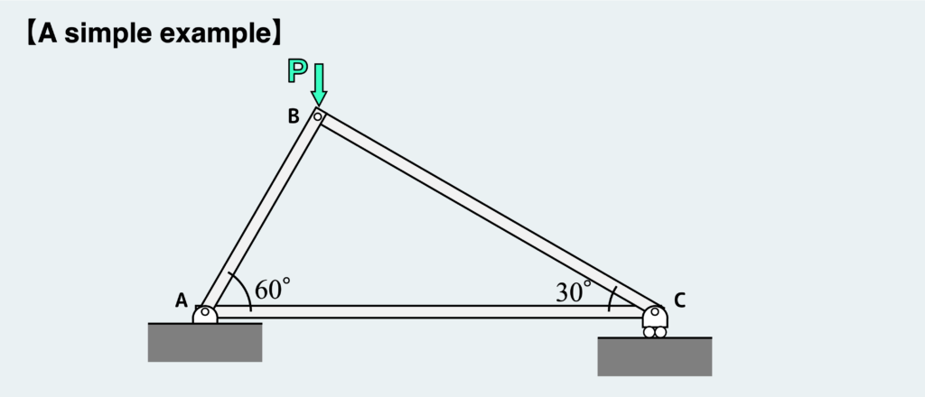
Let’s explore how forces are transmitted in a truss structure using a simple example like the one shown above.
The initial step in tackling the truss problem is to draw a free-body diagram, breaking down all members and nodes into individual pieces.
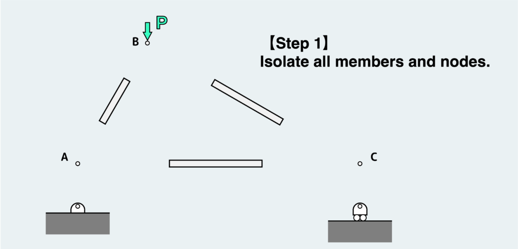
All the nodes and members are disconnected into pieces as depicted in the figure above. Each of these nodes and members must satisfy the equilibrium condition as individual free bodies.
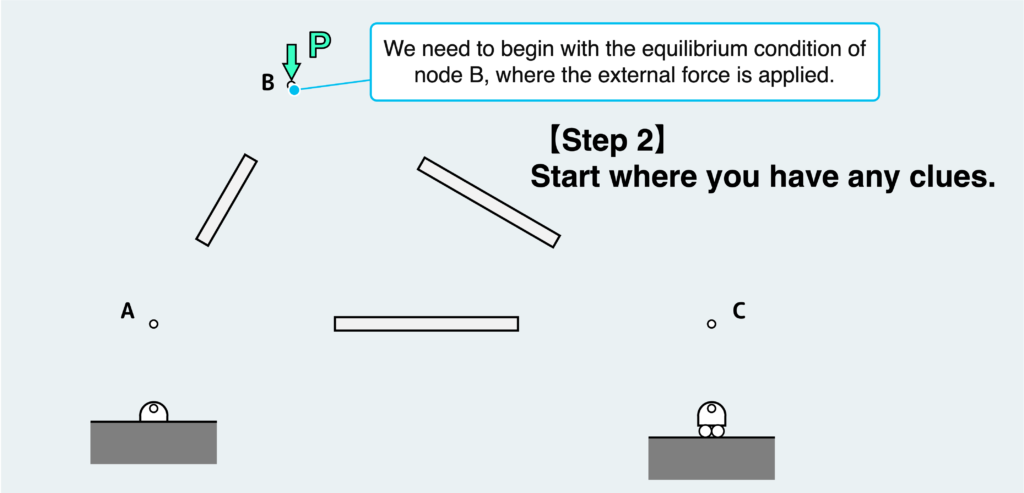
The strategy here is to start where you have any clues. In this scenario, we need to begin with the equilibrium condition of node B, where the external force is applied.
At this stage, we don’t have any information about other free bodies, meaning we don’t have a clue yet.
So, let’s begin with the equilibrium at node B.
When we analyze the equilibrium condition of a node, we don’t need to account for the balance of rotational moments (since the distance from the pivot is zero for all forces). Therefore, our focus is solely on achieving force balance. The crucial aspect here is to apply the concept of vector equilibrium.
For forces to be balanced, the vector sum of all forces must be equal to “0.” This means that when you draw all the vectors connected together, the resultant vector must return to the original starting point.
(* In some cases, considering vector equilibrium may be challenging. In such instances, we should formulate two equilibrium condition equations in the horizontal and vertical directions and solve the simultaneous equations.)
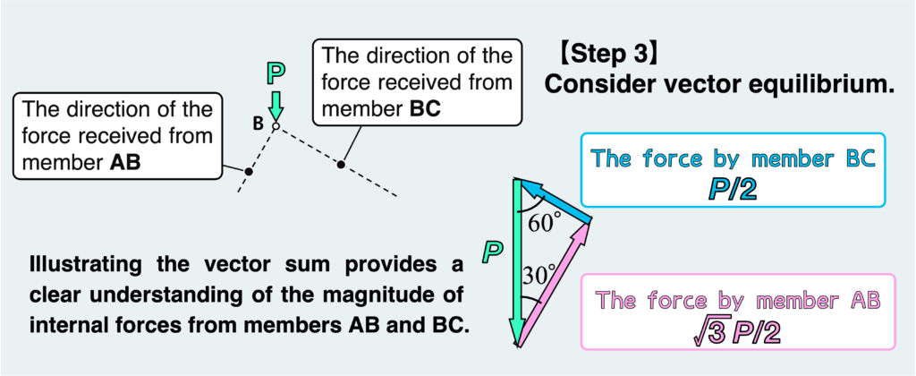
Since only axial force acts on the member, the direction of the force that node B receives from members AB and BC is fixed. We can now determine the magnitude of the force received from AB and BC by drawing a diagram in which the vector sum is “0.”
The figure above, illustrating the vector sum of applied forces on node B, provides a clear understanding of the magnitude of internal forces from members AB and BC.
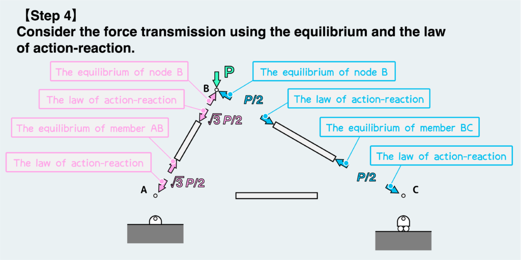
Since the force acting on node B is the force received from the originally connected members AB and BC, the same force is also applied on the member based on the “action-reaction law.” Furthermore, to satisfy the equilibrium condition of the member, the same force acts on the other side of the member. Since this force is received from another connected node of the member, the same force will be applied to the node according to the law of action-reaction.
Now, let’s consider the equilibrium condition of the forces at the next nodal point. You might be wondering whether to start from node A or node C. This confusion can be resolved by focusing on the support method: node A is pin-supported, while node C is supported by a combination of a pin and a roller.
Since node A is pin-supported, it receives reaction forces in two directions, horizontally and vertically. Additionally, it also receives force from member AC. In other words, there are three unknown forces at this point, which cannot be determined by the two equilibrium condition expressions. (By the way, the concept of vector equilibrium is akin to using two equilibrium condition equations for force simultaneously.)
On the other hand, node C has a pin support with a roller, so it receives only a vertical reaction force from the support. Node C also receives a force from member AC, resulting in two unknown forces at work. Therefore, we should prioritize analyzing the balance at node C.
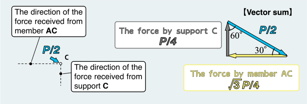
Considering that the reaction force received from the support is only in the vertical direction, let’s examine the vector equilibrium of forces about node C, similar to the case of node B.
By analyzing the vector sum at node C, we can determine the force received from member AC.
Determining the force applied by member AC on node C reveals the force received by member AC from node C, according to the action-reaction law.
By further transferring the force using the equilibrium condition and the law of action-reaction, we can understand how the force is transmitted throughout the truss structure, as illustrated in the figure below.
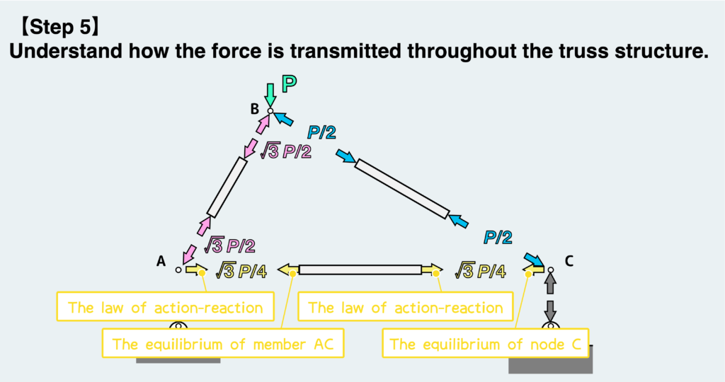
Finally, do we need to consider the equilibrium condition at node A? Its answer is “NO”. There’s no need to consider the equilibrium condition at node A.
Since we’ve already determined the forces transmitted to each member, we can use these forces to analyze the deformation of the truss and the stresses.
Of course, if you want to know the reaction force at node A, you would need to consider the equilibrium condition at node A.
I hope you now grasp the concept of free body in the truss problem, specifically how forces are transmitted.
The key points are (1) only axial forces act on each member, and (2) when considering equilibrium conditions at nodes, the concept of vector equilibrium should be utilized. If you understand these two points well, you’ll comprehend how forces are transmitted within the truss structure.
- A truss structure is characterized by a series of interconnected triangles, with each member linked to others via pins.
- In truss structures, only axial forces (forces along the longitudinal of the member) are present in each member.
- My recommended analysis procedure involves isolating all joints and members, then determining the forces on each member based on vector equilibrium at the joints.
渾身のnoteを書きました!!
「公式は覚えてるのに問題を見たら手が止まる…」
そんなあなたは『解法の型・流れ』を理解できていないのです。材料力学は色々な問題がありますが、実は決まった型に沿って解くことができ、この型こそが材力の基礎であり極意であると言えます。
このnote記事は、本ブログ管理人のぽるこが「材料力学の問題を解く上での型・要点・コツ」を本気でまとめあげました。かなりの大ボリュームかつエッセンスを詰め込んだものですが、1,200円という映画1本分にも満たない価格設定としました。
本ブログに書ききれていない内容も多く含んでおりますので、ぜひ読んでみてください!