
![[thumbnail]_Vol1-2-2en](https://secondinspire.com/wp-content/uploads/thumbnail_Vol1-2-2en-min-940x529.png)

This article serves as the second concrete example of the free body concept, so I will delve into the free body concept involving structural support.
Other examples (some of which are still being written) are as follows.
![[thumbnail]_Vol1-2-1en](https://secondinspire.com/wp-content/uploads/thumbnail_Vol1-2-1en-min-160x160.png) The concept of the free body (vol.1-2-1)
The concept of the free body (vol.1-2-1)
![[thumbnail]_Vol1-2-3en](https://secondinspire.com/wp-content/uploads/thumbnail_Vol1-2-3en-min-160x160.png) The concept of the free body_Truss (vol.1-2-3)
The concept of the free body_Truss (vol.1-2-3)
If you’re interested in learning the basics of free body, please refer to the article below.
![[thumbnail]_Vol1-1en](https://secondinspire.com/wp-content/uploads/thumbnail_Vol1-1en-min-160x160.png) The concept of the free body (vol.1-1)
The concept of the free body (vol.1-1)
Let’s get to the point.
- The reaction force generated depends on the type of support.
- By considering the direction of motion (vertical, horizontal, or rotational) that the fulcrum can support, we can determine the type of reaction force that can be generated.
- Drawing the reaction force correctly is crucial for solving the problem accurately.
- In the case of a statically indeterminate problem, it’s essential to envision the state post-deformation and formulate the conditional equations (also known as the “equations of compatibility”) accordingly.
渾身のnoteを書きました!!
「公式は覚えてるのに問題を見たら手が止まる…」
そんなあなたは『解法の型・流れ』を理解できていないのです。材料力学は色々な問題がありますが、実は決まった型に沿って解くことができ、この型こそが材力の基礎であり極意であると言えます。
このnote記事は、本ブログ管理人のぽるこが「材料力学の問題を解く上での型・要点・コツ」を本気でまとめあげました。かなりの大ボリュームかつエッセンスを詰め込んだものですが、1,200円という映画1本分にも満たない価格設定としました。
本ブログに書ききれていない内容も多く含んでおりますので、ぜひ読んでみてください!
It may seem obvious, but the type of reaction force that a structure receives from a support varies depending on the support method. If this is not well understood, unnecessary forces may be included when drawing the free-body diagram, making it impossible to correctly grasp the internal force transmission. (In fact, you may not be able to solve it at all.)
Let’s examine the types of support methods I will introduce and understand the reaction forces that can act on them.
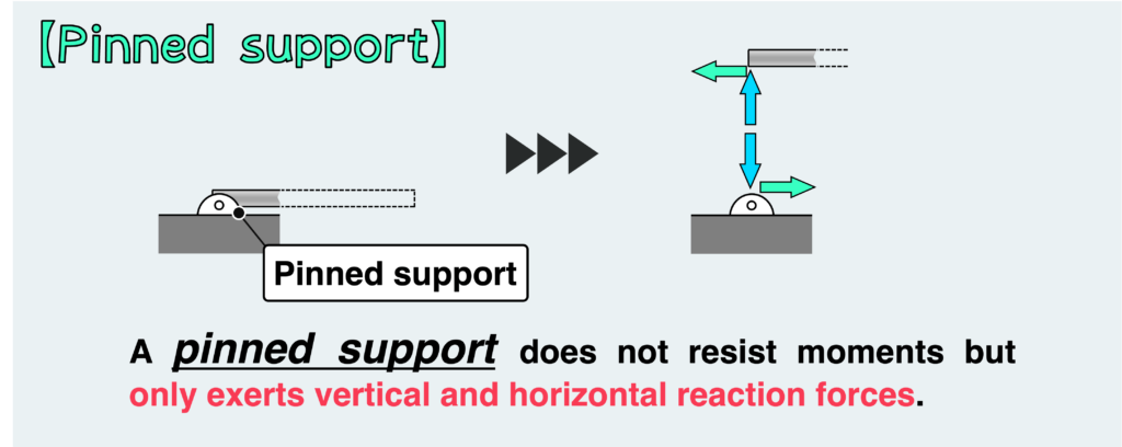
Firstly, I’d like to introduce the pinned support.
The characteristic of a pinned support is that it constrains translation but not rotation. At a support, forces are generated by restricting movement. Therefore, the fact that rotational movement is not restricted means that moments cannot be resisted by the pinned support.
In other words, with a pinned support, moments are not transmitted as reaction forces, and the only reaction forces that can be generated are horizontal and vertical loads.
Similarly, the hinge support also cannot resist moments but only horizontal and vertical loads.
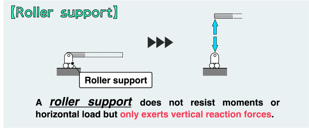
The roller support can be thought of as an extension of the pinned or hinge support described above, with the addition of a roller.
With a roller support, it cannot resist movement in a direction parallel to the ground. In other words, it cannot support moments and horizontal loads because it does not restrain horizontal movement as well as rotation.
In summary, horizontal loads and moments are not transmitted as reaction forces at the roller support, and only vertical loads can occur.
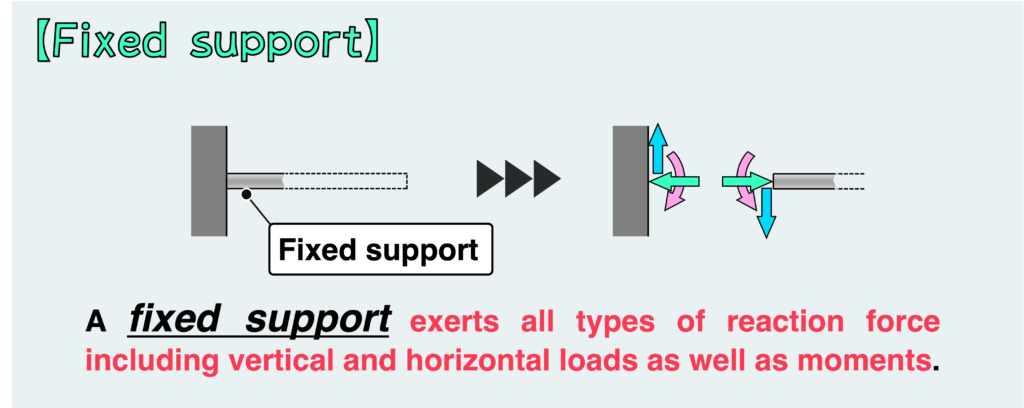
With fixed support, all movements are constrained, allowing it to resist all types of loads, including horizontal and vertical loads as well as moments.
In the free body diagram, you can depict the horizontal and vertical loads, as well as moments, as reaction forces at the fixed support.
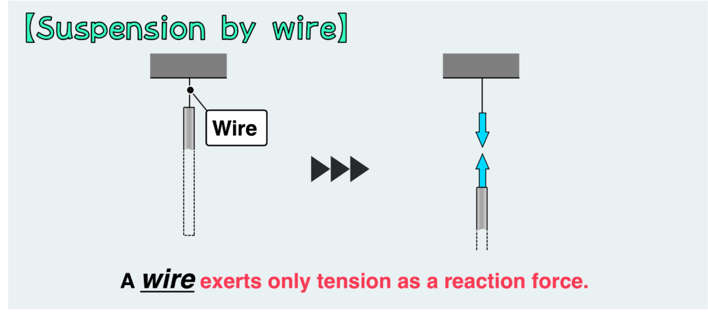
Suspension by wire is not a typical type of structural support, but it’s important to understand its characteristics.
The key aspect of this support is that movement in the compression direction and lateral direction (perpendicular to the longitudinal direction) cannot be constrained due to the thinness of the wire.
This implies that the wire does not resist lateral or compressive loads and moments, but only tension.
However, if the wire is thick enough to possess a certain level of stiffness (to the extent that it may no longer be considered a wire), then this support can also resist lateral or compressive loads.
Now, let’s delve into a specific example using the support methods discussed above.
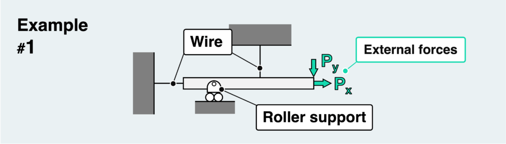
In the scenario shown above, a bar is suspended by wires at two points and supported by a pin with a roller.
Our goal is to determine the reaction force at the support. To do this, we need to isolate the material at the support by cutting it out and extracting it as a free body.
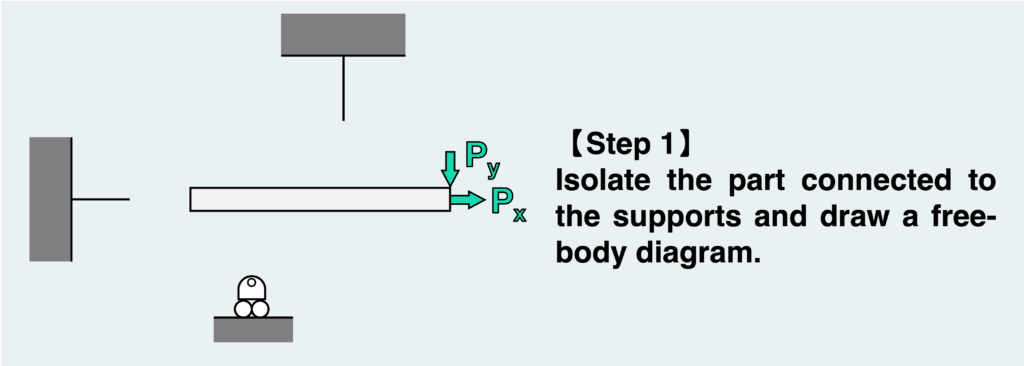
Once you cut out the free body and draw it, it will resemble the figure above. The external force acting on it can be depicted as it is.
However, in this state, the material is not in equilibrium. Consequently, the material will tend to move in the direction of the external force. To counteract this, a reaction force must be exerted from the detached support to maintain balance.
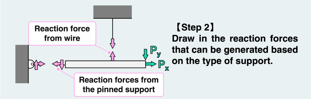
The forces exerted by the originally connected supports are depicted as reaction forces (internal forces). What’s important here is to accurately draw only the forces that can be generated depending on the support method.
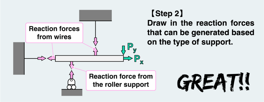
By understanding the characteristic of the support method, we can draw the free body diagram as shown above. The wire resists only tension in its longitudinal direction, as indicated in the figure. The pin + roller cannot support a force parallel to the ground, so only a force perpendicular to the ground can be drawn at this kind of support. The direction of the vertical force exerted by the pin + roller can be assumed in either direction. You are free to choose it as you prefer. However, it’s advisable to select the direction based on your judgment of where the force is likely to be applied, considering the movement and application of force.
Incorrect assumptions are not a serious problem. If an assumption is incorrect, it will result in a negative force when determining this force from the equilibrium condition, and you can realize that your assumption was incorrect.
In this example, there are three unknown forces (reaction forces from the supports), and we can use three equilibrium conditions (horizontal, vertical, and rotational) to solve for these forces. Problems like this, where the number of unknowns matches the number of equations, are called statically determinate problems.
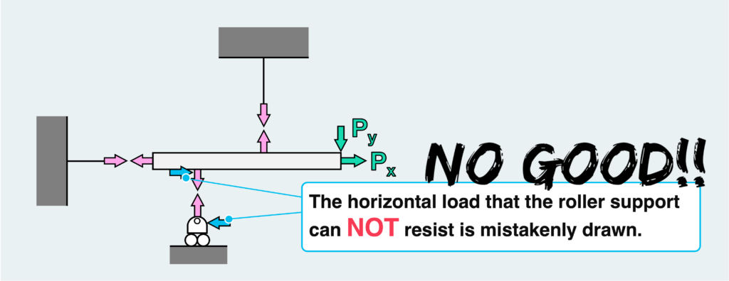
What would happen if we were to draw the reaction forces without considering the type of support? As shown in the figure above, we might mistakenly include a reaction force (horizontal force) that cannot be supported by the pin + roller, or in other words, should not occur.
In this incorrect scenario, there are four unknown forces, but we still have only three equilibrium condition equations available. Consequently, the problem becomes unsolvable.
This highlights the importance of properly understanding and grasping the situation before drawing forces into the free body diagram. Incorrect assumptions or force representations can lead to problems that are originally solvable becoming unsolvable.
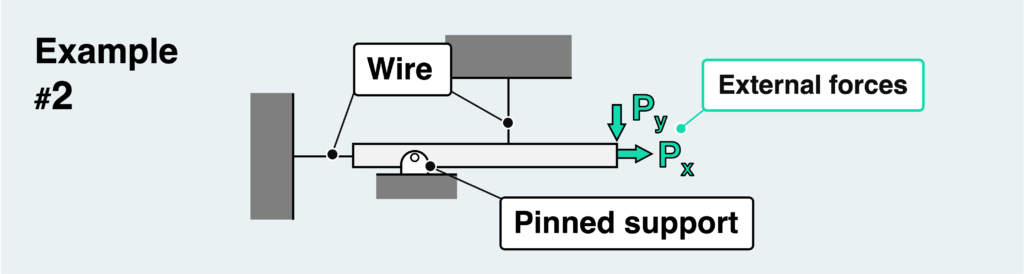
Let us consider the next example.
There isn’t much difference from the first example. The only change is that the roller at the pin support is missing.
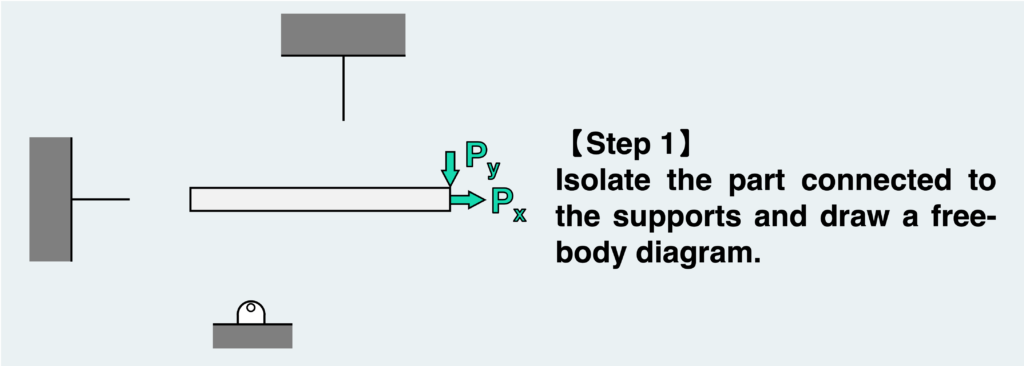
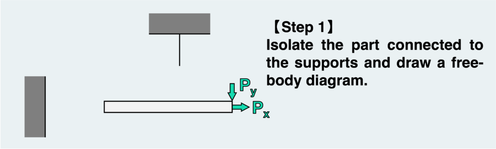
The basic procedure remains the same. Our goal now is to determine the reaction force, so we isolate the part connected to the supports and draw a free body diagram.
In this example, unlike the previous one, the pin does not have a roller attached to it. Therefore, there is a possibility that both vertical and horizontal forces are applied at the pin-supported part.
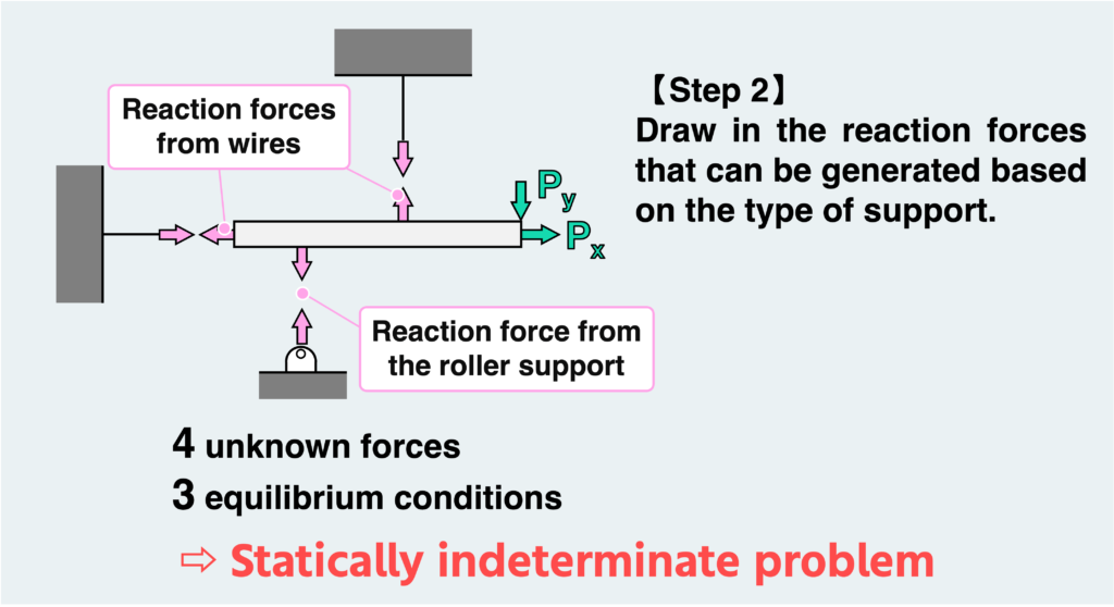
Even though the forces are correctly depicted, there are now four unknown forces, and the equilibrium condition alone is not sufficient to solve the problem. Problems like this, where the unknown internal forces cannot be determined solely by the equilibrium condition, are called statically indeterminate problems.
In this kind of problem, another condition, known as the equations of compatibility, is needed to determine the unknown force. To find these equations, we need to understand the deformation and movement this structure undergoes as a result of external forces, particularly by envisioning where the deformation is constrained.
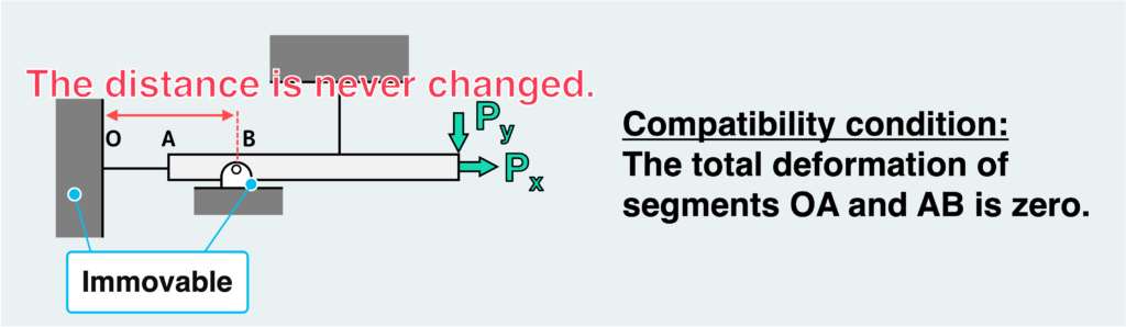
The crucial point in this problem is that the wall and the support cannot move, ensuring that the distance between these two points remains constant. In other words, the total length of wire OA and bar AB in the figure above must always remain unchanged, providing compatibility for this case.
One possibility to meet this requirement is that if OA elongates, AB must compress by the same amount, and conversely, if OA compresses, AB must elongate by the same amount.
Now, is such a deformation possible?
If we consider the internal force transmission between OAB using the concept of free body, the internal force should be transmitted uniformly throughout OAB. This means that if wire OA elongates (i.e., is tensile), bar AB must also elongate. Such a deformation does not satisfy the compatibility condition where the total length of wire OA and bar AB must remain unchanged, indicating that such a deformation is impossible.
Therefore, we need to find another solution that fulfills the compatibility condition.
Another solution is that neither wire OA nor bar AB can deform. This way, we can ensure that the distance between the wall and the support remains unchanged.
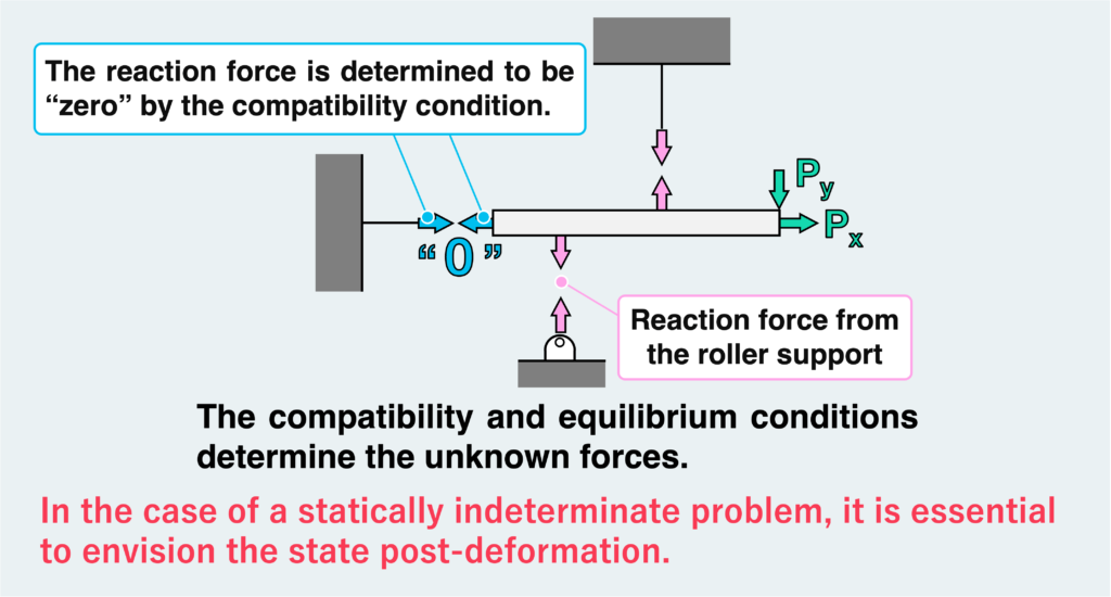
In other words, there should be no force at all between OAB. Therefore, the reaction force from the horizontal wire must be “0”. Once we understand this, we can use the three equilibrium conditions for the remaining three unknown forces to determine all the reaction forces.
Here is the next example.
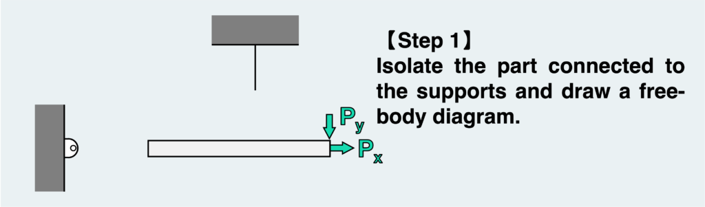
We need to follow the same procedure as always. Cut where the reaction force is to be determined.
Then, we draw in the forces that may occur at the support we have just isolated.
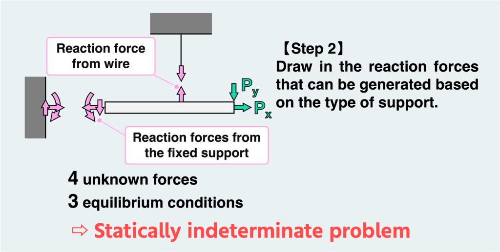
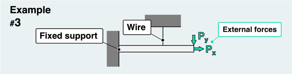
In this problem, we have a fixed support from the wall, so there are three types of reaction forces from the wall: vertical and horizontal loads and moments. So, again, this would be a statically indeterminate problem.
As I explained in the previous example, it is important to envision the state post-deformation in a statically indeterminate problem to obtain the compatibility condition.
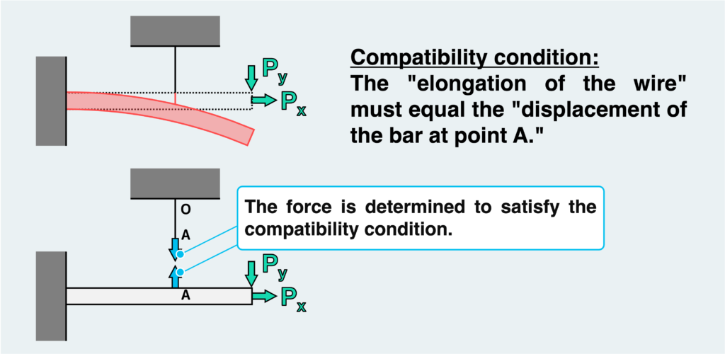
In this problem, the state post-deformation is as shown in the figure above. By carefully examining this figure, we can identify where the constraints on the deformation occur. The constraints must be expressed in a mathematical formula.
In conclusion, since the tip of the wire and the bar are connected at point A, the “elongation of the wire” must be equal to the “displacement of the bar at point A.” If we express each amount of deformation using the unknown force and create an equation that states they are equal, we have a conditional expression for the deformation (equation of compatibility).
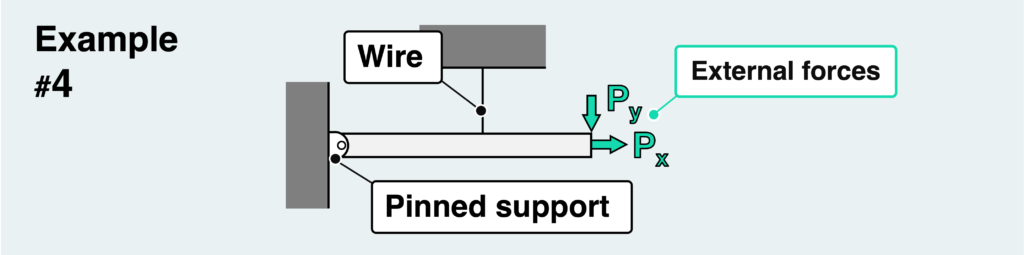
Now for the last example. This is a version of the fixed support of the wall in the previous example #3 that has been replaced by a pinned support.
A pinned support cannot resist moments, so the only two reaction forces received from the pinned support are the vertical and horizontal loads. Since this is a statically determinate problem, all the reaction forces can be determined by the equilibrium conditions alone.
In this article, we have looked in detail at what difference the support method makes when drawing a free body diagram.
Although it may seem like a minor detail, understanding it correctly is crucial for solving problems accurately. I encourage you to review this carefully to enhance your understanding.
- The reaction force generated depends on the type of support.
- By considering the direction of motion (vertical, horizontal, or rotational) that the fulcrum can support, we can determine the type of reaction force that can be generated.
- Drawing the reaction force correctly is crucial for solving the problem accurately.
- In the case of a statically indeterminate problem, it’s essential to envision the state post-deformation and formulate the conditional equations (also known as the “equations of compatibility”) accordingly.
渾身のnoteを書きました!!
「公式は覚えてるのに問題を見たら手が止まる…」
そんなあなたは『解法の型・流れ』を理解できていないのです。材料力学は色々な問題がありますが、実は決まった型に沿って解くことができ、この型こそが材力の基礎であり極意であると言えます。
このnote記事は、本ブログ管理人のぽるこが「材料力学の問題を解く上での型・要点・コツ」を本気でまとめあげました。かなりの大ボリュームかつエッセンスを詰め込んだものですが、1,200円という映画1本分にも満たない価格設定としました。
本ブログに書ききれていない内容も多く含んでおりますので、ぜひ読んでみてください!