

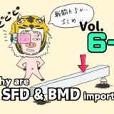
In the previous article, we talked about why shear force diagrams (SFD) and bending moment diagrams (BMD) matter.
Now, let’s move on to the practical part—how to actually draw SFDs and BMDs.
If you follow a clear set of steps, anyone can draw them correctly and consistently. Once you get the hang of it, it becomes almost mechanical. So take your time and try to master it.
Explore more articles on SFD and BMD here!
How to Draw SFD & BMD: Worked Example and Step-by-Step Solution
How Different Loads Appear in Shear Force and Bending Moment Diagrams (SFD and BMD)
How to Draw Shear Force and Bending Moment Diagrams (SFD & BMD) Step by Step
Shear Force Diagram & Bending Moment Diagram (SFD/BMD): What They Are and Why They Matter
Here’s the step-by-step process for drawing SFDs and BMDs:
- Calculate support reactions
(For all problems except cantilever beams, first determine the reactions at supports or walls.) - Check whether you need to divide the beam into sections is needed
Decide whether the loading or conditions change along the beam. - Cut the beam at an arbitrary position
Let the distance from the left end to this section be x, and draw the free-body diagram. - Apply equilibrium equations
Solve for the internal forces (shear force F and bending moment M) at the cut section, and express them as functions of x. - Plot the results
Draw the SFD and BMD using F(x) and M(x).
渾身のnoteを書きました!!

「公式は覚えてるのに問題を見たら手が止まる…」
そんなあなたは『解法の型・流れ』を理解できていないのです。材料力学は色々な問題がありますが、実は決まった型に沿って解くことができ、この型こそが材力の基礎であり極意であると言えます。
このnote記事は、本ブログ管理人のぽるこが「材料力学の問題を解く上での型・要点・コツ」を本気でまとめあげました。かなりの大ボリュームかつエッセンスを詰め込んだものですが、1,200円という映画1本分にも満たない価格設定としました。
本ブログに書ききれていない内容も多く含んでおりますので、ぜひ読んでみてください!
Contents
- Let’s Master How to Draw SFDs and BMDs with a Simple Example!
- Follow This Procedure and Anyone Can Draw Them!
- Step 1: Calculate support reactions
- Step 2: Check Whether Dividing into Sections Is Needed
- Step 3: Draw the Free-Body Diagram
- Step 4: Solve for F and M Using Equilibrium
- Step 5: Draw the SFD and BMD
- Summary
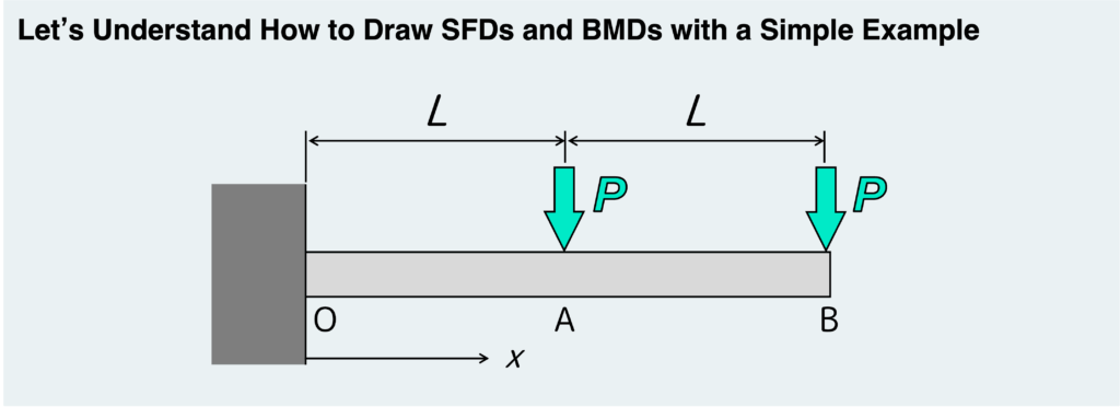
Using the very simple example shown above, let’s go through the process of drawing SFDs and BMDs step by step.
Follow the procedure, and you should be able to draw them without getting lost.
By following the steps below, you should be able to draw SFDs and BMDs accurately without making mistakes.
Isolate the entire beam from its supports and treat it as a free body.
Then, use the equilibrium equations to calculate the support reactions.
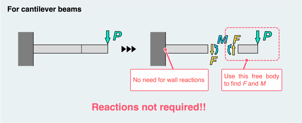
For cantilever beams, you can skip this step.
Scan the beam from left to right.
Whenever there is a point where the loading or conditions change, you need to divide the beam into sections.
Cut the beam at an arbitrary location and create a free body.
At the cut section, you can introduce the internal forces: shear force F and bending moment M.
Their directions (positive directions) should be assigned according to the rule—don’t worry, we’ll go over the rules later.
At this stage, it does not matter whether the actual internal forces act in those directions or not.
Let the distance from the left end of the beam to the cut section be x.
Apply the equilibrium equations to the free body you just created.
This allows you to determine the internal forces acting at the cut section located at position x.
The shear force F and bending moment M are obtained as functions of x.
If you divided the beam into multiple sections in Step 2, repeat Steps 3 and 4 for each section.
Plot the results on graphs with x on the horizontal axis and either F or M on the vertical axis.
At key points—such as boundaries between sections—substitute specific values of x to calculate F and M, and use those values to sketch the diagrams.
For beams other than cantilever beams, start with this step.
If you’re dealing with a cantilever beam, you can skip it.
Let’s briefly look at why.
In the case of a cantilever beam, the process of cutting the beam at an arbitrary position and solving for the internal forces looks like the figure below.
In this type of problem, the reaction force comes from the fixed wall.
However, unless you cut the root (fixed end) of the beam, that reaction force never appears in your free-body diagram.
And as you can see, by simply considering the equilibrium of the free body on the free-end side, you can directly obtain the shear force F and bending moment M.
So, there’s no need to worry about what’s happening at the fixed end—you can completely ignore the support reactions.
On the other hand, what about beams that are not cantilever beams? For example, beams supported at both ends or beams with intermediate supports, like the ones shown below.
In these cases, when you cut the beam at an arbitrary location and consider the internal forces at that section, the situation looks like this.
You end up with two possible free bodies, but in either case, there are three unknowns: shear force F, bending moment M, and reaction force R.
However, you only have two equilibrium equations available (force balance in the vertical direction and moment balance).
With three unknowns and only two equations, you simply can’t solve for everything.
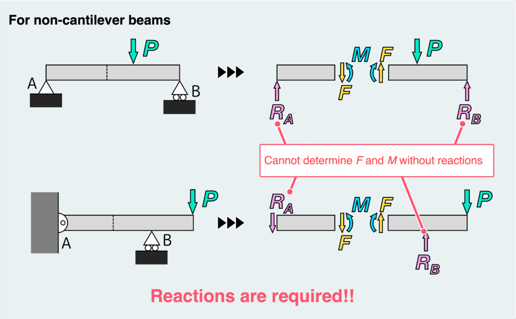
That’s why, for these types of problems, you need to first isolate the entire beam as a free body (separating it from the supports or walls) and calculate the support reactions in advance.
Next, determine whether you need to divide the beam into sections.
In simple terms, scan the beam from left to right.
If there is any point where the conditions change, you need to divide the beam at that location.
So, what kind of “changes” are we talking about?
Typical examples are shown in the figure below.
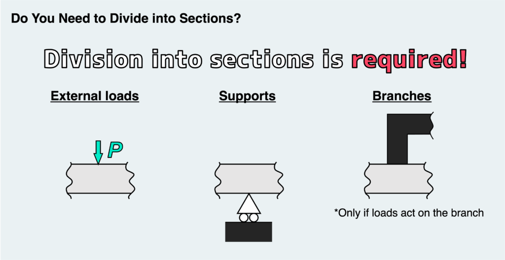
What this really means is: whenever a force or moment is applied somewhere along the beam, you need to divide it into sections.
This includes obvious cases where external loads are visibly applied. It also includes supports, since reaction forces act there.
And if the beam has branches, any external load acting on a branch will be transmitted to the junction, causing forces to act at that point as well.
On the other hand, there are cases where dividing into sections is not necessary, as shown below.
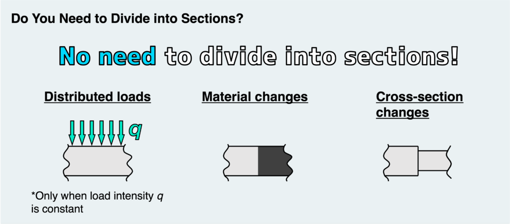
First, you don’t need to worry about distributed loads—they do not require dividing the beam.
A common source of confusion is changes in material properties or cross-sectional shape.
These may seem like significant changes, but when it comes to drawing SFDs and BMDs, you can safely ignore them.
This is because SFDs and BMDs represent how internal forces vary along the beam.
Changes in material or geometry do not affect how those internal forces are transmitted.
(However, they do have a significant impact on stress and deformation, so you need to take them into account when analyzing those.)
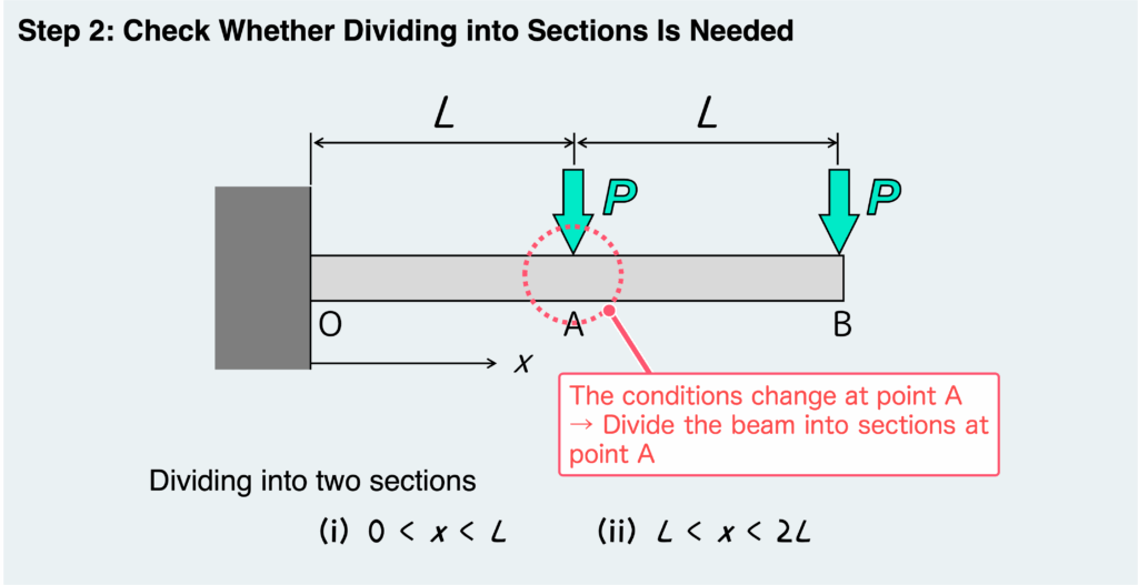
Now, let’s apply Step 2 to this specific example.
In this problem, a concentrated load P is applied at point A in the middle of the beam.
Therefore, we need to divide the beam into sections at this point.
In other words, we consider two regions:
- (i)
- (ii)
Here, x represents the position where we make a virtual cut in the beam—that is, it indicates where we are evaluating the internal forces.
So, in region (i), we consider the internal forces acting in segment OA, and in region (ii), those in segment AB.
By the way, as a rule, the origin of x (i.e., ) is set at the left end of the beam.
Next, in Step 3, draw the free-body diagram.
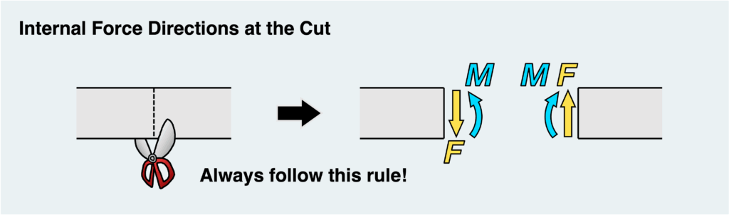
The key point here is not to get the directions of the shear force F and bending moment M wrong when you place them at the cut section.
When drawing SFDs and BMDs, the positive directions are defined strictly.
Personally, I think that in problems other than SFDs and BMDs, you can assume whatever directions you like when introducing unknown internal forces.
(Some instructors may tell you to always take tension as positive and assign directions accordingly.)
But when it comes to SFDs and BMDs, you must always place F and M in the prescribed directions.
I know this part can feel confusing at first.
But honestly, there’s no need to overthink it. Once you cut a section, just draw them mechanically: one fixed pattern for the left face, and another fixed pattern for the right face.
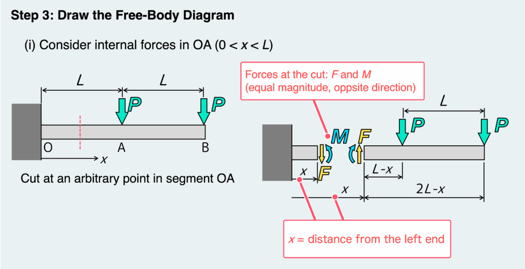
Now, let’s draw the free-body diagram using the same example from Step 2.
First, consider the first region we defined—case (i).
Draw a diagram by cutting the beam at an arbitrary point somewhere within segment OA.
At the cut section, place the shear force F and bending moment M as we discussed earlier.
At this point, the distance from the left end to the cut section is x, so it’s a good idea to label this in the diagram as well.
This gives you a free-body diagram like the one shown below.
Strictly speaking, you should also draw the free-body diagram for the other case, (ii).
However, we’ll move on to Step 4 first and come back to case (ii) later.
Next, use the free-body diagram you just created to determine F and M from the equilibrium equations.
In this example, only one free body is available, so we’ll consider the equilibrium of the right side (the free-end side).
In some cases, however, you can draw two possible free bodies. When that happens, it’s best to choose the one that makes the calculations easier.
Either way, no matter which free body you use, you’ll end up with the same results for F and M.
For this example, the equilibrium equations for the free body are shown below.
As you can see, the resulting F and M are expressed as functions of x.
We’ll use these expressions in Step 5 to draw the SFD and BMD.
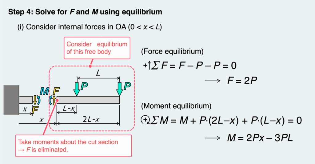
Here’s a useful tip.
When writing the moment equilibrium equation, you need to choose a point about which to take moments.
A good choice is the cut section itself.
Why? Because if you take moments about the cut section, the shear force F does not appear in the equation.
This is because the moment arm of F becomes zero, so it simply drops out of the equation.
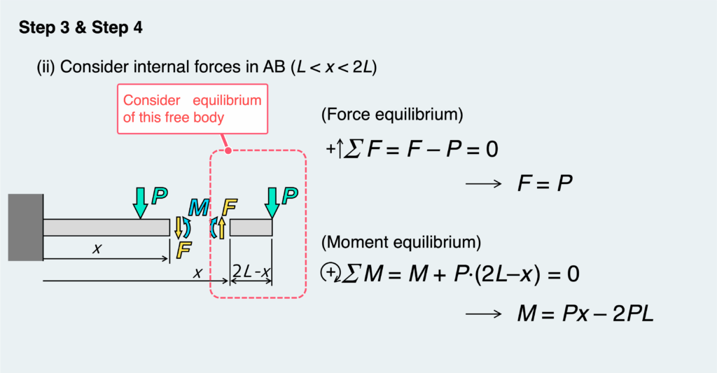
Now, let’s do the same for the second region—case (ii).
By repeating Step 3 and Step 4 for each section, you can determine the shear force F and bending moment M as functions of position x over the entire beam.
For case (ii), the free-body diagram, the equilibrium equations, and the resulting expressions for F and M are shown below.
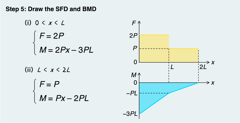
Now we’ve reached the final step.
Let’s plot the shear force F and bending moment M obtained in Step 4.
At this stage, all you need to do is graph the functions, so as long as you have a basic understanding of math, you should be fine.
While it’s not a strict rule, it’s a good idea to label key points on the vertical axis with specific values or expressions.
In the example below, (which corresponds to point A on the beam) is one such key point.
By substituting into the expressions for F and M, you can determine their values at that location and mark them on the graph.
In SFDs and BMDs, you’ll often see characteristic features such as sudden jumps (discontinuities) and sharp corners.
These patterns correspond to what is physically happening in the beam at those locations.
So, understanding this relationship not only makes it easier to draw the diagrams, but also helps you catch mistakes after you’ve finished.
We’ll cover these characteristic patterns of SFDs and BMDs in the next article, so be sure to check that out as well.
And with that, the SFD and BMD are complete!
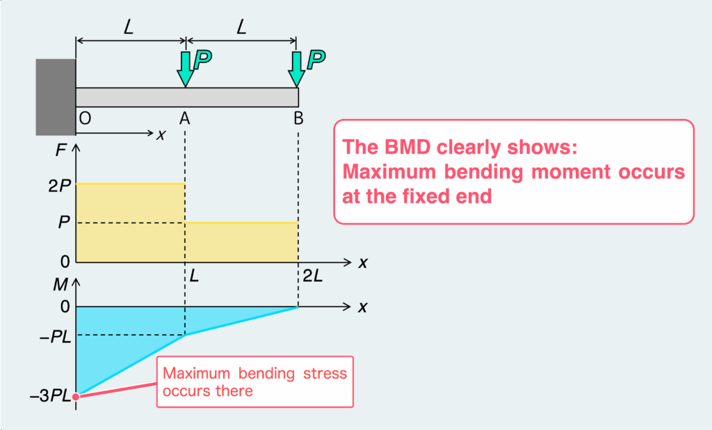
By the way, as explained in the previous article, the purpose of SFDs and BMDs is to visually understand where and how loads are acting, and in particular, where the maximum load occurs.
In this example, the BMD makes it immediately clear that the maximum bending moment occurs at the fixed end.
This also means that the bending stress in the beam reaches its maximum at that location.
Of course, this example is very simple, so you can probably predict this behavior even without drawing the BMD.
However, for more complex problems, accurately drawing SFDs and BMDs becomes essential for understanding the stresses acting within the material.
You might be thinking, “Wait, the moment at the fixed end is negative—does that still count as the maximum?”
But that’s not an issue.
The sign of the bending moment simply indicates the direction of bending (i.e., which side of the beam is in tension).
Whether the moment is positive or negative, a larger magnitude means a larger bending stress.
In other words, when comparing bending moments, you should focus on their absolute values.
(Of course, if the beam has different properties on the top and bottom—such as being significantly weaker in tension on one side—then the direction of the bending moment does matter and should be taken into account.)
In this article, we went through a step-by-step method for drawing SFDs and BMDs.
If you follow this procedure, you should be able to draw them correctly for any problem.
From here, the best thing you can do is practice with a variety of problems and get comfortable with the process.
In the next article, we’ll explore the key characteristics of SFDs and BMDs and the typical patterns that appear in these diagrams.
If you want to take your understanding to the next level, be sure to check it out.
Explore more articles on SFD and BMD here!
How to Draw SFD & BMD: Worked Example and Step-by-Step Solution
How Different Loads Appear in Shear Force and Bending Moment Diagrams (SFD and BMD)
How to Draw Shear Force and Bending Moment Diagrams (SFD & BMD) Step by Step
Shear Force Diagram & Bending Moment Diagram (SFD/BMD): What They Are and Why They Matter
Here’s the step-by-step process for drawing SFDs and BMDs:
- Calculate support reactions
(For all problems except cantilever beams, first determine the reactions at supports or walls.) - Check whether you need to divide the beam into sections is needed
Decide whether the loading or conditions change along the beam. - Cut the beam at an arbitrary position
Let the distance from the left end to this section be x, and draw the free-body diagram. - Apply equilibrium equations
Solve for the internal forces (shear force F and bending moment M) at the cut section, and express them as functions of x. - Plot the results
Draw the SFD and BMD using F(x) and M(x).
渾身のnoteを書きました!!
「公式は覚えてるのに問題を見たら手が止まる…」
そんなあなたは『解法の型・流れ』を理解できていないのです。材料力学は色々な問題がありますが、実は決まった型に沿って解くことができ、この型こそが材力の基礎であり極意であると言えます。
このnote記事は、本ブログ管理人のぽるこが「材料力学の問題を解く上での型・要点・コツ」を本気でまとめあげました。かなりの大ボリュームかつエッセンスを詰め込んだものですが、1,200円という映画1本分にも満たない価格設定としました。
本ブログに書ききれていない内容も多く含んでおりますので、ぜひ読んでみてください!