


When thinking about bending, why do we suddenly need something more complicated, like the area moment of inertia?
What does it actually mean?
This is where many students start to get confused.
When you first encounter bending problems, you quickly realize that understanding stress and deformation isn’t so straightforward.
And sooner or later, you come across a term that seems to control everything: the area moment of inertia.
At first, it can feel a bit abstract.
There are tables of formulas for different shapes, and it’s tempting to just plug numbers in and move on.
But if you don’t really understand what it means, it’s easy to misuse it—and sometimes even reach the wrong conclusion.
So in this article, we’ll focus on what the area moment of inertia actually represents, and how to think about it in a practical way.
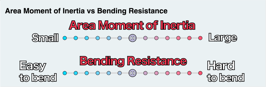
- The area moment of inertia, I, measures how resistant a cross-section is to bending.
It plays a similar role to cross-sectional area in tension and compression. - Larger I → harder to bend
- Smaller I → easier to bend
- The area moment of inertia depends only on the shape of the cross-section, not on the material.
- It is used to calculate bending stress, as well as deflection and slope of beams.
- Shapes that place more material farther from the neutral plane have a larger area moment of inertia.
As a result, they are more resistant to bending (harder to bend).
渾身のnoteを書きました!!

「公式は覚えてるのに問題を見たら手が止まる…」
そんなあなたは『解法の型・流れ』を理解できていないのです。材料力学は色々な問題がありますが、実は決まった型に沿って解くことができ、この型こそが材力の基礎であり極意であると言えます。
このnote記事は、本ブログ管理人のぽるこが「材料力学の問題を解く上での型・要点・コツ」を本気でまとめあげました。かなりの大ボリュームかつエッセンスを詰め込んだものですが、1,200円という映画1本分にも満たない価格設定5/5までは30%OFFで840円としました。
本ブログに書ききれていない内容も多く含んでおりますので、ぜひ読んでみてください!
Contents
- What Does the Area Moment of Inertia Represent?
- Comparison with Tension and Compression
- Effect of the Area Moment of Inertia — More or Less Resistance to Bending?
- Relationship Between Cross-Sectional Shape and Area Moment of Inertia
- How Is It Used? — Calculating Bending Stress and Deflection
- Summary
In general, how difficult a material is to deform (often referred to as stiffness) depends on two things:
- the material itself
- and the shape and size of the cross-section
The effect of the material is usually easy to understand.
For example, if you take two beams with the same shape—one made of rubber and the other made of steel—the rubber will deform much more under the same load, while the steel will hardly deform at all.
This difference comes from the material properties, which are represented by parameters such as Young’s modulus, E, and the shear modulus, G.
But even if the material is the same, changing the cross-section shape will also change how much the beam deforms.
In general, a beam with a larger cross-section tends to be more resistant to deformation.
The area moment of inertia is one of the key parameters that describes this effect.
To better understand and develop an intuitive feel for the area moment of inertia, let’s compare it with the case of tension and compression.
In problems involving tension and compression, we didn’t need anything as complicated as the area moment of inertia. However, even in these cases, the resistance to deformation still depends on the cross-sectional shape.
So what parameter did we use to represent this effect?
That would be the cross-sectional area.
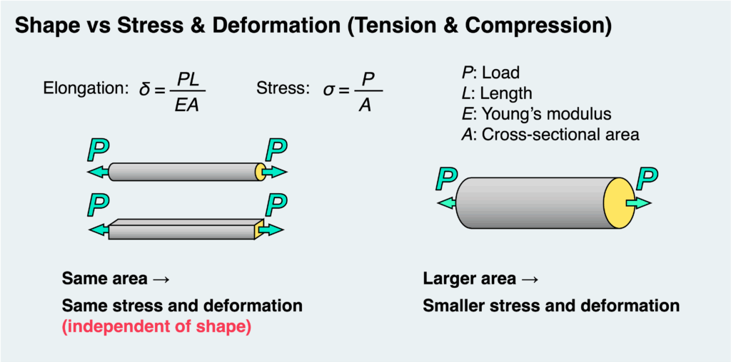
As you may recall from the formulas for stress and deformation (elongation or contraction), a larger cross-sectional area results in lower stress and smaller deformation. Conversely, a smaller area leads to higher stress and greater deformation.
Tension and compression are quite straightforward, and their behavior is relatively easy to understand intuitively.
So why, in bending problems, do we need the area moment of inertia instead of just the cross-sectional area?
Let’s look at a simple example.
Most people have tried bending a thin plastic sheet at some point. Consider holding such a sheet horizontally versus vertically and trying to bend it.
Even though the cross-sectional area is the same in both cases, the resistance to bending is dramatically different. The vertically oriented case is clearly much harder to bend.
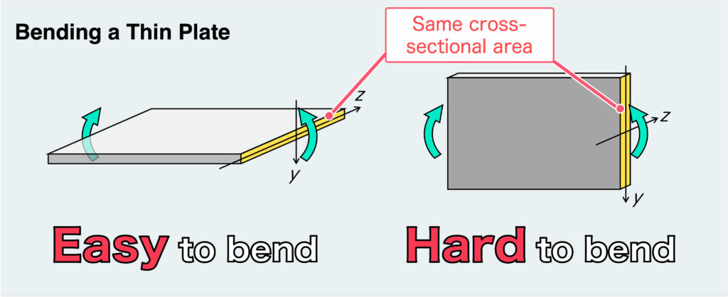
This shows that resistance to bending cannot be determined by cross-sectional area alone—it depends strongly on how the cross-section is arranged relative to the bending axis.
More precisely, it depends on the geometry of the cross-section relative to the neutral axis (the z-axis in the figure).
That’s why, unlike in tension and compression, cross-sectional area alone is not sufficient to describe bending behavior. Instead, we use the area moment of inertia.
In summary, the area moment of inertia is a parameter that represents how resistant a cross-section is to bending, based on its geometry and dimensions with respect to the neutral axis.
Now that we have a general understanding of the area moment of inertia, let’s clarify how its magnitude relates to resistance to bending.
When the area moment of inertia is large, the structure becomes more resistant to bending under the same load (bending moment). In other words, the resulting deformation is smaller. In many cases, the bending stress is also reduced.
Therefore, increasing the area moment of inertia generally leads to a safer design—assuming there are no constraints such as size, weight, or cost.
On the other hand, when the area moment of inertia is small, the structure bends more easily. This results in larger deformation and, in many cases, higher bending stress. As a result, the risk of failure increases.
Let’s take a look at the figure below.
Here, we are considering bending in the direction shown, so focus on the coordinate system and the definition of the area moment of inertia.
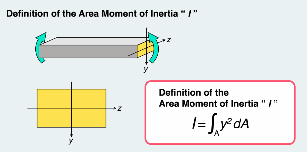
Mathematically, the area moment of inertia is defined as the integral of over the cross-section. But don’t worry too much about the math here.
What matters is this:
The area moment of inertia tells us how far the material in the cross-section is distributed from the neutral axis (the z-axis in this case), specifically in the y-direction.
In other words, for this type of bending, spreading the cross-section in the horizontal direction (z-direction) doesn’t have much effect. What really matters is how far the material extends in the vertical direction (y-direction).
When you try to bend a thin plate, you’ll find that it’s much harder to bend when it’s standing upright than when it’s laid flat. As shown in the figure below, even though the cross-sectional area is the same, the area moment of inertia—and therefore the resistance to bending—is completely different depending on the orientation.
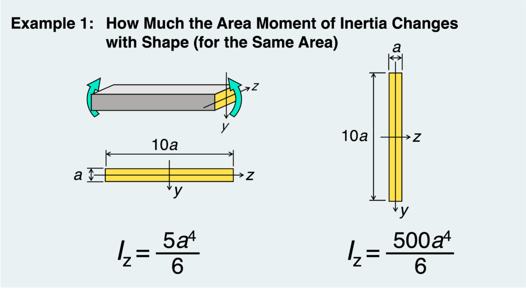
For bending about this axis, the vertical dimension plays a dominant role.
Roughly speaking, a taller cross-section leads to a larger area moment of inertia and greater resistance to bending.
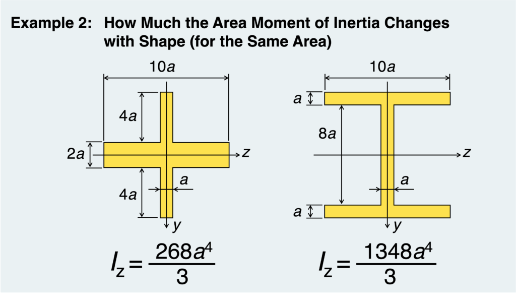
Also, even if the overall proportions stay the same—as in the example shown below—the area moment of inertia becomes larger when more of the area is distributed farther away from the neutral axis.
Take a look at the next example to see this more clearly.
(In this case as well, bending is assumed about the same axis, with the z-axis as the neutral axis.)
Just like the cross-sectional area in tension and compression, the area moment of inertia is used to calculate stress and deformation in bending.
For a beam subjected to a bending moment, the resulting stress and deflection can be expressed as shown below. For comparison, the corresponding formulas for tension and compression are also included.
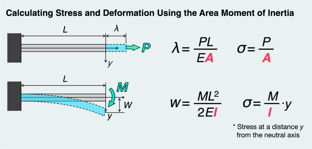
If you focus on the form of the equations—without worrying too much about the details—you’ll notice that they look quite similar to those for tension and compression.
In the same way that a larger cross-sectional area reduces stress and deformation in tension and compression, a larger area moment of inertia leads to smaller bending stress and deflection.
In practice, calculating bending stress and deflection requires correctly evaluating the area moment of inertia for different cross-sectional shapes. To do that, you need a deeper understanding of how the area moment of inertia works.
We’ll take a closer look at how it is used in bending stress calculations in a separate article.
The term area moment of inertia may sound unfamiliar, and it can be hard to grasp what it really means at first. But there’s no need to be intimidated by it.
At its core, it’s simply a parameter that describes how resistant a cross-section is to bending based on its shape. You can think of it as the bending counterpart of cross-sectional area in tension and compression—that perspective often makes it much easier to understand.
In this article, we haven’t gone into the details of how to use the area moment of inertia in actual calculations. To explore that further, we would need to take a closer look at stress distribution in bending, which is a slightly deeper topic.
So we’ll stop here for now.
In the next article, we’ll dive into bending stress in more detail. Now that you have a better sense of what the area moment of inertia represents, you’ll be in a great position to follow along—so be sure to check it out.
- The area moment of inertia, I, measures how resistant a cross-section is to bending.
It plays a similar role to cross-sectional area in tension and compression. - Larger I → harder to bend
- Smaller I → easier to bend
- The area moment of inertia depends only on the shape of the cross-section, not on the material.
- It is used to calculate bending stress, as well as deflection and slope of beams.
- Shapes that place more material farther from the neutral plane have a larger area moment of inertia.
As a result, they are more resistant to bending (harder to bend).
渾身のnoteを書きました!!
「公式は覚えてるのに問題を見たら手が止まる…」
そんなあなたは『解法の型・流れ』を理解できていないのです。材料力学は色々な問題がありますが、実は決まった型に沿って解くことができ、この型こそが材力の基礎であり極意であると言えます。
このnote記事は、本ブログ管理人のぽるこが「材料力学の問題を解く上での型・要点・コツ」を本気でまとめあげました。かなりの大ボリュームかつエッセンスを詰め込んだものですが、1,200円という映画1本分にも満たない価格設定5/5までは30%OFFで840円としました。
本ブログに書ききれていない内容も多く含んでおりますので、ぜひ読んでみてください!